


11
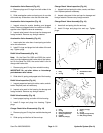
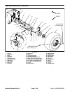
Traction Pump Assembly
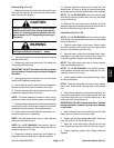
1. Make sure all parts are cleaned thoroughly and free
of dirt and debris.
2. Secure ball bearing onto shaft with retaining ring.
Press assembly into variable housing. Snap retaining
ring into housing to secure bearing and shaft (Fig. 49).
IMPORTANT: Make sure not to damage the face sur-
face on the cavity side of the variable housing.
3. Position variable housing so the large cavity is up.
Press needle bearings into each side of the variable
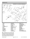
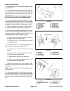
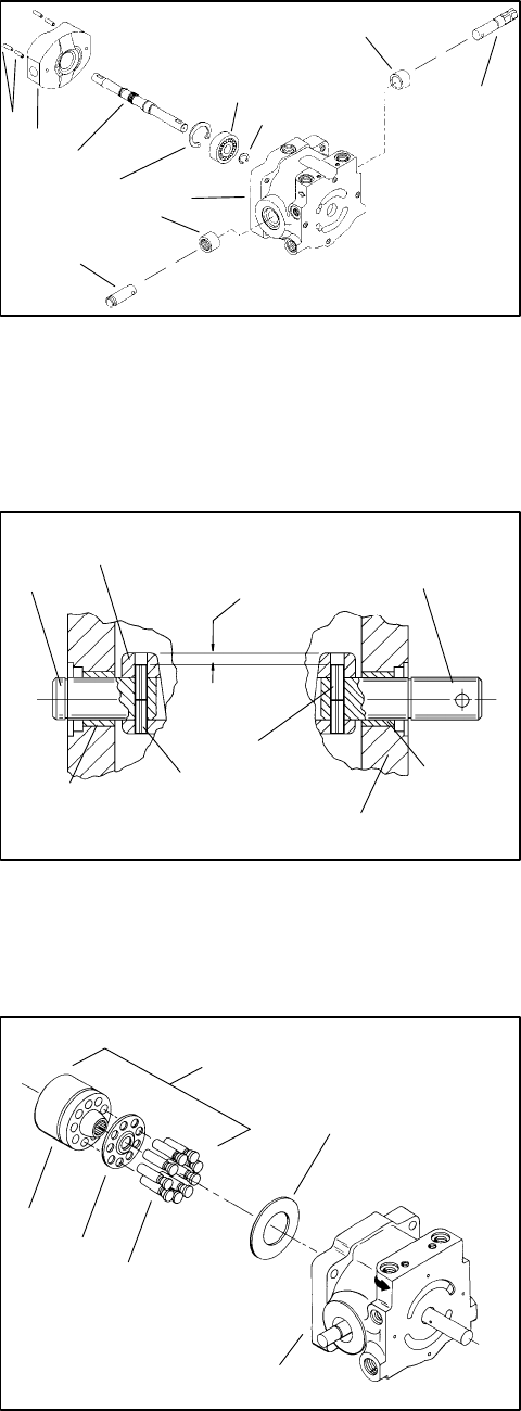
Figure 49
housing. Make sure bearings are flush to 1/64 inch (0.40
4
10
1
7
6
5
2
8
9
3
1. Variable housing
7. Retaining ring
mm) below the counter bore for the lip seals (Fig. 49).
2. Spring pins
8. Ball bearing
3. Control shaft
9. Retaining ring
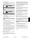
4. Place swashplate into variable housing with the
4. Trunnion shaft
10. Needle bearing
11. Journal bearing
counter bore for the thrust plate facing up (Fig. 49).
5. Swashplate
6. Shaft
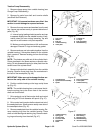
5. Make sure control shaft is positioned to the proper
side of the variable housing before installing. The con-
2
trol shaft should be installed on the side of the pump that
will accept the pump control linkage (Fig. 49).
4
A. Insert control and trunnion shafts through the
housing into the swash plate bores.
B. Make sure holes in the swashplate and shafts
are aligned properly.
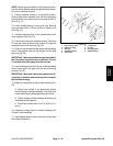
6. Insert new spring pins through the swashplate and
into the control and trunnion shafts (Fig. 50).
5
1
1
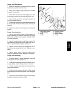
1/4 INCH (6.4 mm)
7
3
6
A. Install first pin until the second pin can be
started.
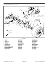
Figure 50
5. Variable housing
B. Drive both pins in until the last pin is 1/4 inch
1. Spring pin
2. Swashplate 6. Needle bearing
(6.35 mm) below the swash plate.
3. Control shaft 7. Journal bearing
4. Trunnion shaft
C. Repeat steps A and B on the other shaft.
D. Make sure swashplate swings freely and to 15
o
each way from the center position.
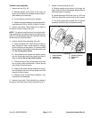
7. Lubricate thrust plate with clean hydraulic fluid.
5
Make sure contact surface for the piston shoes is facing
up (Fig. 51).
NOTE: Piston placement in the bores requires no spe-
1
2
3
cial orientating.
4
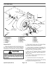
8. Lubricate cylinder block, spider, and piston assem-
blies with clean hydraulic oil. Insert piston assemblies
through the spider and into the bores. Make sure spider
and spider pivot contact surfaces align properly (Fig.
51).
6
Figure 51
1. Cylinder block 4. Piston assemblies
2. Cylinder block assembly 5. Thrust plate
3. Spider 6. Variable housing
Hydraulic System (Rev. A) Page 4 – 54 Sand Pro 2020/3020/5020