


Sand Pro 2020/3020/5020Hydraulic System (Rev. A) Page 4 – 44
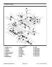
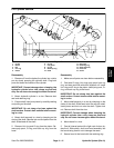
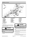
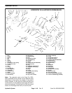
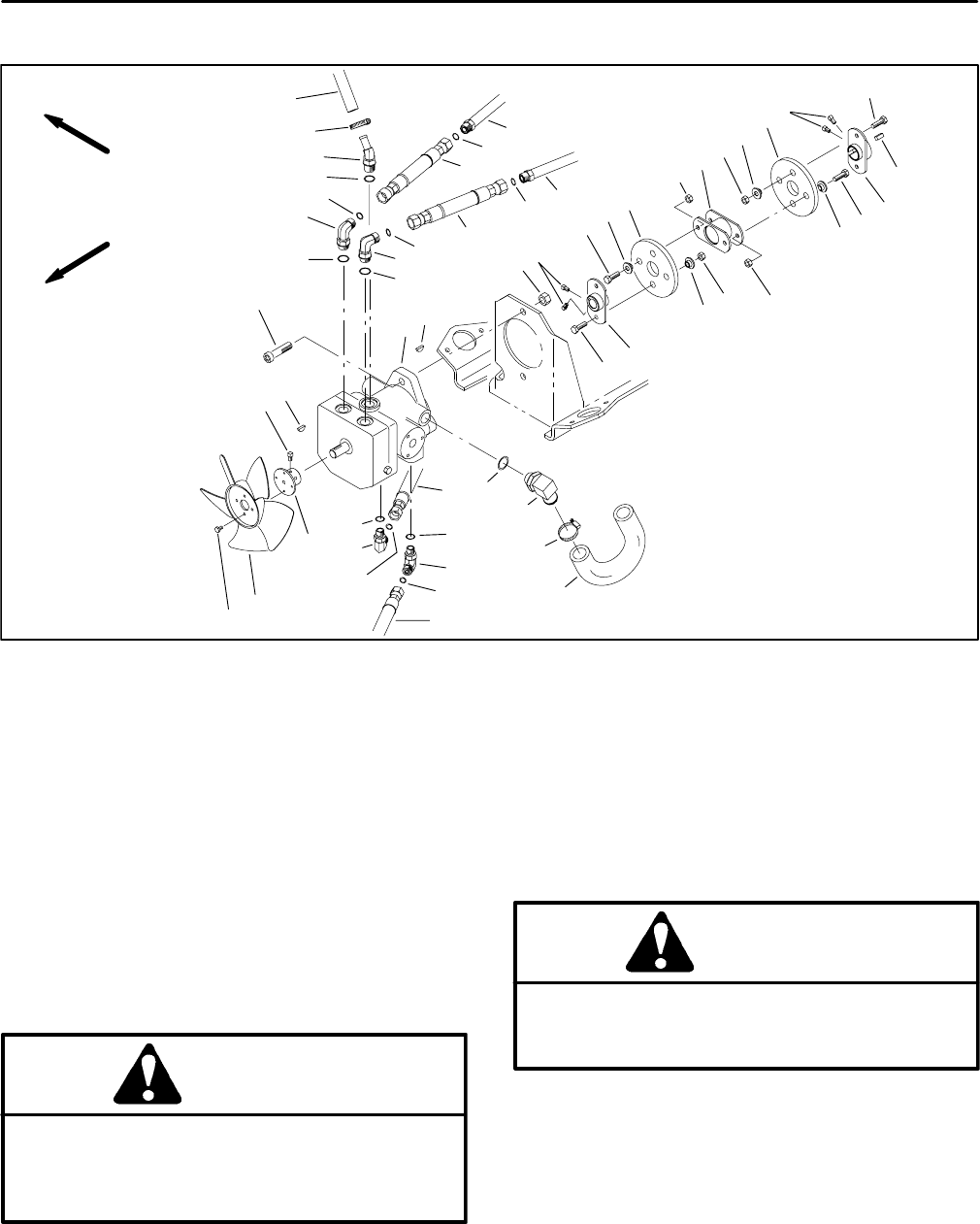
Hydrostat (SP 5020)
1. Hydraulic hose (to front motor)
2. O–ring
3. Hydraulic tube
4. Not used
5. Hydraulic tube
6. 90
o
hydraulic fitting
7. O–ring
8. Hydrostat
9. Woodruff key
10. Lock nut
11. Set screw
12. Hex nut
13. Coupler spacer
14. Rubber coupler
15. Cap screw
16. Coupling
17. Square key
18. Engine hub
19. Pump hub
20. Socket head screw
21. Hydraulic hose (To lift valve)
22. O–ring
23. 90
o
hydraulic fitting
24. O–ring
25. Hydraulic hose (from oil cooler)
26. Not used
27. Fan hub
28. Cooling fan
29. Cap screw
30. Hydraulic hose (from oil filter)
31. Hose clamp
32. 90
o
hydraulic fitting
33. O–ring
34. 45
o
hydraulic fitting
35. Hydraulic hose (to tank)
36. Hydraulic hose (from rear motors)
Figure 33
31
32
33
34
31
35
1
2
3
36
5
6
7
8
9
10
16
17
18
19
20
21
22
23
24
25
27
28
29
30
11
12
13
14
15
2
2
11
11
9
12
12
12
13
13
13
14
15
15
15
22
23
24
2
6
7
7
FRONT
RIGHT
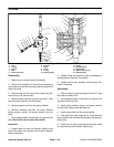
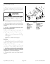
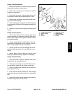
Removal (Fig. 33)
1. Before removing any parts from the hydraulic sys-
tem, park machine on a level surface, set brake, lower
attachment, and stop engine.
CAUTION
Operate all hydraulic controls to relieve system
pressure and avoid injury from pressurized hy-
draulic oil. Controls must be operated with the
ignition switch in OFF. Remove key from the igni-
tion switch.
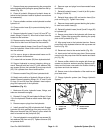
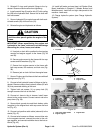
2. Pivot seat up. Remove left and right side panels
from the machine. Remove left fender and seat (see Left
Fender (Seat Base) Removal in Chapter 6 – Wheels,
Brakes, and Miscellaneous).
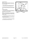
CAUTION
The muffler and exhaust pipe may be hot. To
avoid possible burns, allow engine and exhaust
system to cool before working near the muffler.
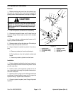
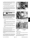
3. Disconnect wire harness as follows: disconnect
blue wire from magneto terminal, disconnect blue wire
from voltage regulator, disconnect red/white wire from
fuel solenoid (Fig. 45).
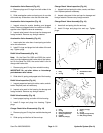
4. Disconnect red positive cable cable (solenoid) from
the starter. Remove lock nut and cap screw securing
black ground wire and black battery cable (negative) to
the engine block. Pull cable and harness clear of the en-
gine (Fig. 47).