


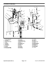
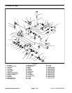
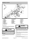
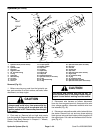
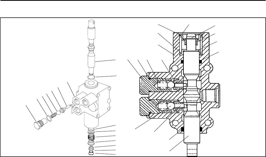
Lift Valve
1
2
3
4
5
6
7
12
15
14
1 2
8
9
9
10
4
11
12
13
14
15
3 5
6
9
8
7
9
10
11
13
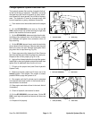
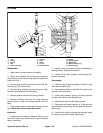
Figure 27
1. Plug
6. Cam pin
11. Spring
2. O–ring
7. Body
12. Spring retainer
3. Spring
8. Spool
13. Spacer float
4. Ball
9. O–ring
14. Spool retaining ring
5. Check valve seat
10. Spring retainer
15. Retaining ring
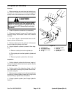
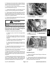
Disassembly
1. Wash valve in solvent and dry thoroughly.
2. Mount valve carefully in a vise so that the retaining
ring is facing up and the mounting pads are against the
jaws of the vise.
3. Remove plug and O–ring from the valve body. Re-
move spring, ball, and cam pin.
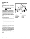
4. Remove spool retaining ring from the spool. Push
and twist spool carefully out of the body.
5. Remove spacer float from the spring retainer.
6. Remove retaining ring from the body. Remove
spring retainer, spring, and spring retainer from the
body.
7. Use hooked scribe to remove both O–rings from the
body. Be careful not to scratch bore finish.
Inspection
1. Inspect spool for wear and flatness. Wear on one
side of the spool may indicate a bent spool. Replace
spool if necessary.
2. Inspect check valve seat for wear and damage of
sealing surface. Replace if necessary.
3. Inspect ball for wear, damage, and flat spots. Re-
place if necessary.
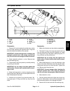
Reassembly
1. Clean and dry all parts thoroughly. Coat all O–rings
with clean hydraulic fluid.
2. Use hooked scribe to install both O–rings into the
grooves of the body bore.
3. Install spring retainer, spring, and spring retainer
into the body. Secure with retaining ring.
4. Install spacer float into the spring retainer.
5. Coat spool with clean hydraulic oil. Push and twist
spool carefully into the body. Secure spool with spool re
-
taining ring.
6. Install cam pin, ball, and spring into the body. Install
O–ring and plug into the body. Tighten plug.
Hydraulic System (Rev. A) Page 4 – 38 Sand Pro 2020/3020/5020