


Traction Pump
Disassembly
1. Remove charge pump from variable housing (see
Charge Pump Disassembly).
2. Remove lip seals from shaft and trunnion shafts
(see Shaft Seal Removal).
IMPORTANT: All exposed surfaces are critical. Use
caution to avoid damage to exposed surfaces.
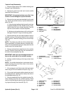
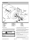
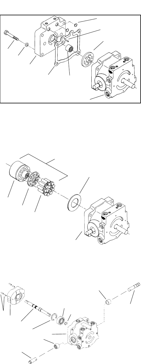
3. Remove four cap screws and washers from the end
cap. Loosen cap screws evenly to prevent distortion of
parts (Fig. 45).
A. Internal spring loading should cause the end cap
to separate slightly from the variable housing. If sep
-
aration does not occur during loosening, tap end
cap with a soft hammer until parts separate.
B. Make sure valve plate does not fall and become
damaged. Discard O–rings and end cap gasket.
4. Remove end cap and valve plate together from the
variable housing. If valve plate remains on the cylinder
block, remove it. Remove locating pin from the end cap
(Fig. 45).
NOTE: The pistons may slide out of the cylinder block.
Piston placement in the bores requires no special orien
-
tating. Do not disassemble spring or other parts from the
center bore of the cylinder block.
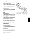
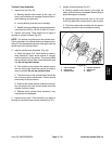
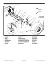
5. Remove cylinder block assembly from the variable
housing. Remove thrust plate from the counterbore in
the face of the swashplate (Fig. 46).
IMPORTANT: Make sure not to damage the face sur-
face on the cavity side of the variable housing.
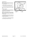
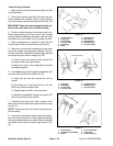
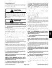
6. Position variable housing so the large cavity faces
up (Fig. 47).
NOTE: The variable housing has a cast recess that al-
lows the spring pins to be driven free of the trunnion
shaft and control shaft.
7. Drive spring pin out of the trunnion shaft and control
shaft using a 3/16 inch diameter drift punch (Fig. 47).
8. Drive control and trunnion shafts outward and out of
the swashplate bore. Shafts remove easily once clear of
the swashplate bore (Fig. 47).
9. Remove swashplate from the variable housing. Re-
move retaining ring from the variable housing. Press
shaft out with bearing and retaining ring. Remove retain
-
ing ring and bearing from the shaft (Fig. 47).
1
3
8
4
7
5
6
9
2
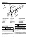
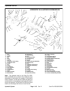
Figure 45
1. Cap screw
6. Locating pin
2. Washer
7. O–rings
3. End cap
8. End cap gasket
4. Variable housing
9. Needle bearing
5. Valve plate
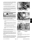
Figure 46
2
1
3
4
5
6
1. Cylinder block 4. Piston assemblies
2. Cylinder block assembly 5. Thrust plate
3. Spider 6. Variable housing
4
10
1
7
6
5
2
8
9
11
3
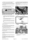
Figure 47
1. Variable housing
7. Retaining ring
2. Spring pins
8. Ball bearing
3. Control shaft
9. Retaining ring
4. Trunnion shaft
10. Needle bearing
5. Swashplate
11. Journal bearing
6. Shaft
Hydraulic System (Rev. A) Page 4 – 52 Sand Pro 2020/3020/5020