


GE Multilin 489 Generator Management Relay 4-27
4 SETPOINTS 4.6 S5 CURRENT ELEMENTS
4
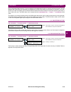
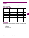
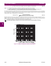
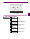
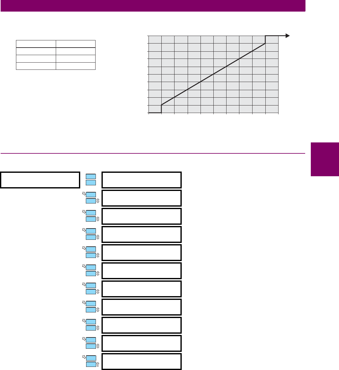
The 489 phase overcurrent restraint voltages and restraint characteristic are shown below:
Figure 4–2: VOLTAGE RESTRAINT CHARACTERISTIC
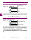
4.6.6 NEGATIVE SEQUENCE OVERCURRENT
PATH: SETPOINTS ÖØ S5 CURRENT ELEMENTS ÖØ NEGATIVE SEQUENCE
Rotor heating in generators due to negative sequence current is a well known phenomenon. Generators have very specific
capability limits where unbalanced current is concerned (see ANSI C50.13). A generator should have a rating for both con-
tinuous and also short time operation when negative sequence current components are present.
NEGATIVE SEQUENCE
[ENTER] for more
NEGATIVE SEQUENCE
ALARM: Off
Range: Off, Latched, Unlatched
ASSIGN ALARM
RELAYS (2-5): ---5
Range: Any combination of Relays 2 to 5
NEG. SEQUENCE ALARM
PICKUP: 3% FLA
Range: 3 to 100% FLA in steps of 1
NEGATIVE SEQUENCE
ALARM DELAY: 0.5 s
Range: 0.1 to 100.0 s in steps of 0.1
NEGATIVE SEQUENCE
ALARM EVENTS: Off
Range: On, Off
NEGATIVE SEQUENCE
O/C TRIP: Off
Range: Off, Latched, Unlatched
ASSIGN TRIP
RELAYS (1-4): 1---
Range: Any combination of Relays 1 to 4
NEG. SEQUENCE O/C
TRIP PICKUP: 8% FLA
Range: 3 to 100% FLA in steps of 1
NEG. SEQUENCE O/C
CONSTANT K: 1
Range: 1 to 100 in steps of 1
NEG. SEQUENCE O/C
MAX. TIME: 1000 s
Range: 10 to 1000 s in steps of 1
NEG. SEQUENCE O/C
RESET RATE: 227.0 s
Range: 0.0 to 999.9 s in steps of 0.01
808792A3.CDR
Phase-PhaseVoltage / Rated Phase-PhaseVoltage
CurvePickup Multiplier
0
0 0.1 0.2 0.3 0.4 0.5 0.6 0.7 0.8 0.9 1
0.1
0.2
0.4
0.5
0.6
0.7
0.8
0.9
1
0.3
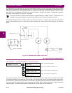
CURRENT VOLTAGE
IAVab
IBVbc
ICVca
PhaseOvercurrent Restraint Voltages:
ENTER
ESCAPE
ð
ð
MESSAGE
ESCAPE
MESSAGE
ESCAPE
MESSAGE
ESCAPE
MESSAGE
ESCAPE
MESSAGE
ESCAPE
MESSAGE
ESCAPE
MESSAGE
ESCAPE
MESSAGE
ESCAPE
MESSAGE
ESCAPE
MESSAGE
ESCAPE