


GE Multilin 489 Generator Management Relay 7-7
7 TESTING 7.2 HARDWARE FUNCTIONAL TESTS
7
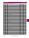
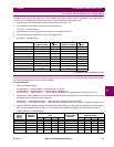
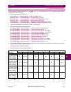
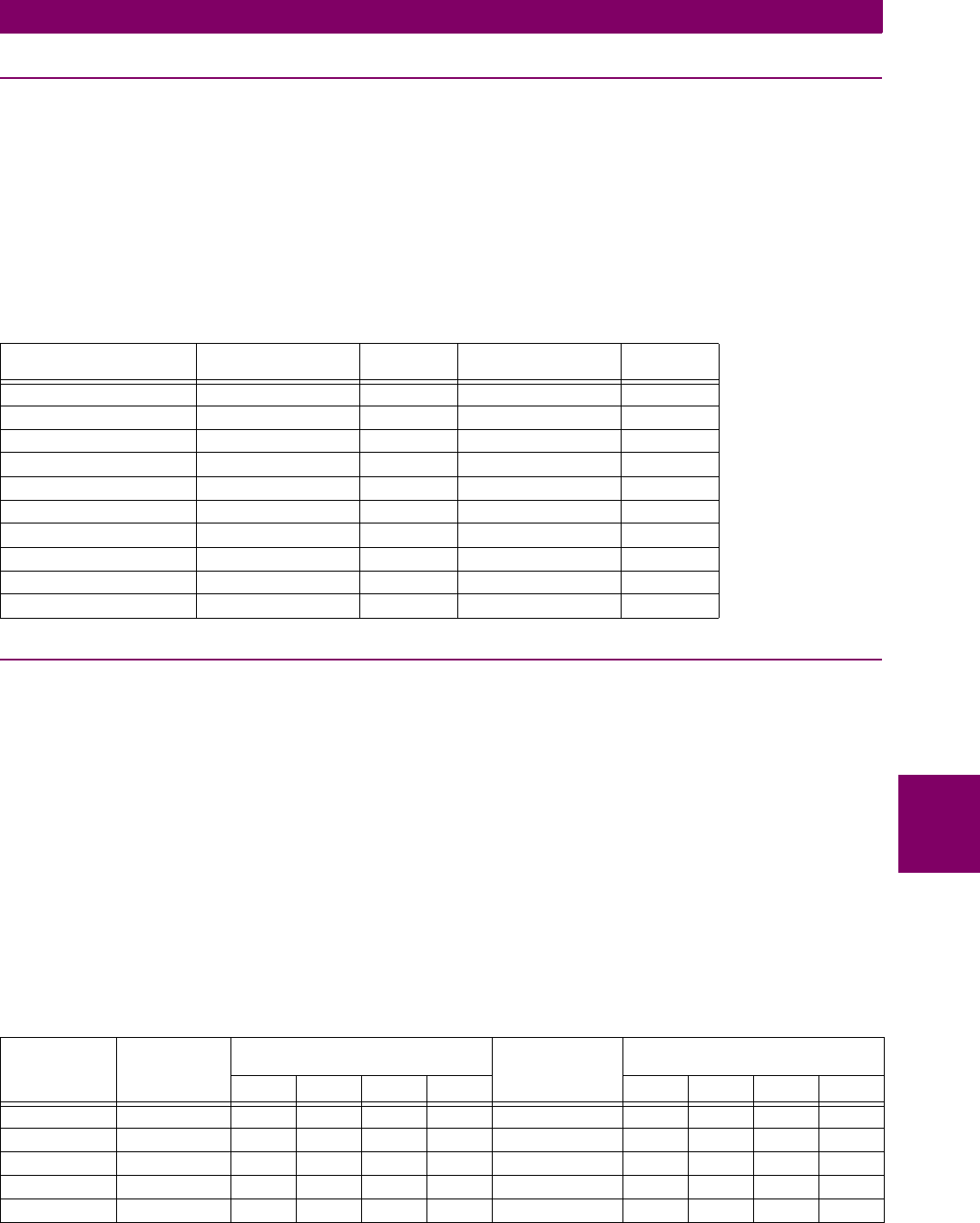
7.2.7 DIGITAL INPUTS AND TRIP COIL SUPERVISION
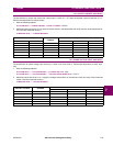
The digital inputs and trip coil supervision can be verified easily with a simple switch or pushbutton. Verify the SWITCH
+24 V DC with a voltmeter. Perform the steps below to verify functionality of the digital inputs.
1. Open switches of all of the digital inputs and the trip coil supervision circuit.
2. View the status of the digital inputs and trip coil supervision in:
A1 STATUS ÖØ DIGITAL INPUTS
3. Close switches of all of the digital inputs and the trip coil supervision circuit.
4. View the status of the digital inputs and trip coil supervision in:
A1 STATUS ÖØ DIGITAL INPUTS
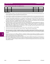
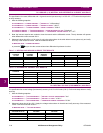
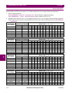
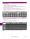
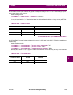
7.2.8 ANALOG INPUTS AND OUTPUTS
The specification for analog input and analog output accuracy is ±1% of full scale. Perform the steps below to verify accu-
racy. Verify the Analog Input +24 V DC with a voltmeter.
4 to 20 mA INPUTS:
1. Alter the following setpoints:
S11 ANALOG I/O ÖØ ANALOG INPUT1 Ö ANALOG INPUT1: "4-20 mA"
S11 ANALOG I/O ÖØ ANALOG INPUT1 ÖØ ANALOG INPUT1 MINIMUM: "0"
S11 ANALOG I/O ÖØ ANALOG INPUT1 ÖØ ANALOG INPUT1 MAXIMUM: "1000" (repeat all for Analog Inputs 2 to 4)
2. Analog output values should be ±0.2 mA on the ammeter. Measured analog input values should be ±10 units. Force
the analog outputs using the following setpoints:
S12 TESTING ÖØ TEST ANALOG OUTPUT Ö FORCE ANALOG OUTPUTS FUNCTION: "Enabled"
S12 TESTING ÖØ TEST ANALOG OUTPUT ÖØ ANALOG OUTPUT 1 FORCED VALUE: "0%" (enter %, repeat for Outputs 2 to 4)
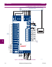
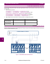
3. Verify the ammeter readings and the measured analog input readings. For the purposes of testing, the analog input is
fed in from the analog output (see Figure 7–1: Secondary Current Injection Testing). View the measured values in:
A2 METERING DATA Ö ANALOG INPUTS
INPUT EXPECTED STATUS
(SWITCH OPEN)
PASS
FAIL
EXPECTED STATUS
(SWITCH CLOSED)
PASS
FAIL
ACCESS Open Shorted
BREAKER STATUS Open Shorted
ASSIGNABLE INPUT 1 Open Shorted
ASSIGNABLE INPUT 2 Open Shorted
ASSIGNABLE INPUT 3 Open Shorted
ASSIGNABLE INPUT 4 Open Shorted
ASSIGNABLE INPUT 5 Open Shorted
ASSIGNABLE INPUT 6 Open Shorted
ASSIGNABLE INPUT 7 Open Shorted
TRIP COIL SUPERVISION No Coil Coil
ANALOG
OUTPUT
FORCE
VALUE
EXPECTED
AMMETER
READING
MEASURED AMMETER READING
(MA)
EXPECTED
ANALOG INPUT
READING
MEASURED ANALOG INPUT
READING (UNITS)
1234 1234
0% 4 mA 0 units
25% 8 mA 250 units
50% 12 mA 500 units
75% 16 mA 750 units
100% 20 mA 1000 units