


GE Multilin 489 Generator Management Relay 7-3
7 TESTING 7.2 HARDWARE FUNCTIONAL TESTS
7
7.2HARDWARE FUNCTIONAL TESTS 7.2.1 OUTPUT CURRENT ACCURACY
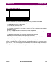
The specification for output and neutral end current input is ±0.5% of 2 × CT when the injected current is less than 2 × CT.
Perform the steps below to verify accuracy.
1. Alter the following setpoint:
S2 SYSTEM SETUP Ö CURRENT SENSING Ö PHASE CT PRIMARY: "1000 A"
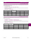
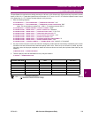
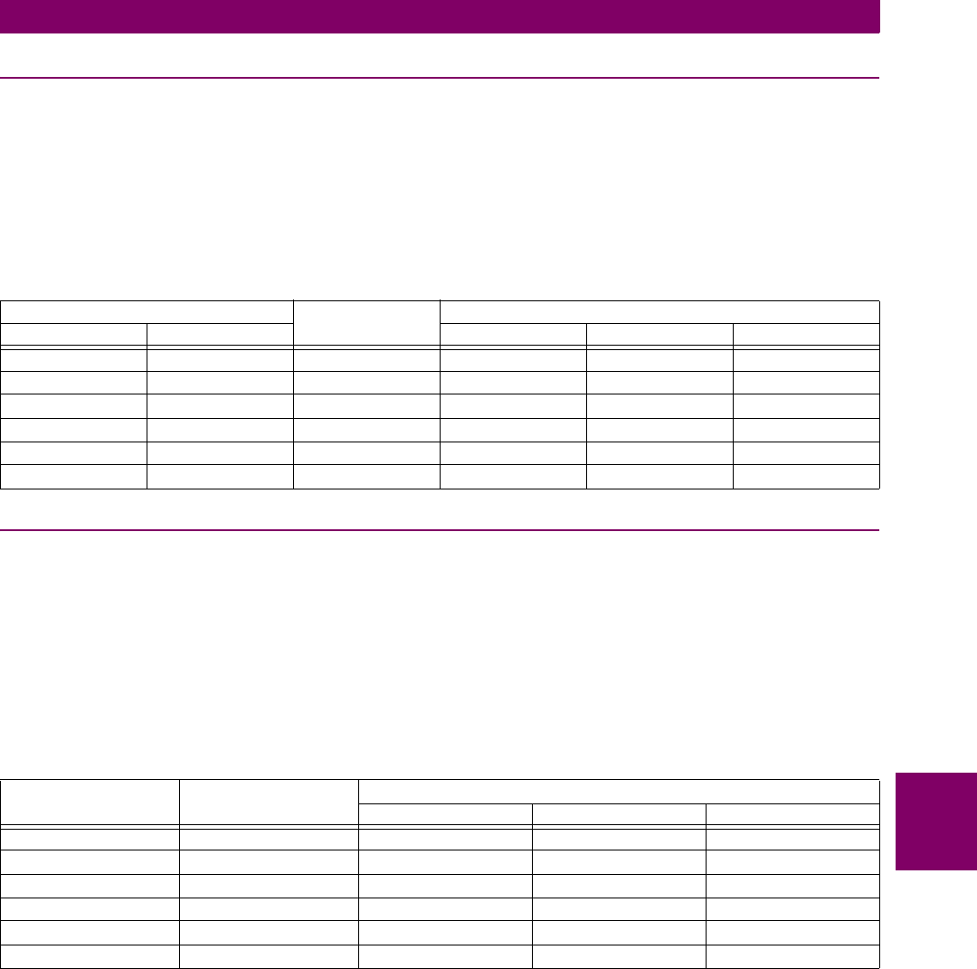
2. Measured values should be ±10 A. Inject the values shown in the table below and verify accuracy of the measured val-
ues. View the measured values in:
A2 METERING DATA ÖØ CURRENT METERING
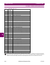
7.2.2 PHASE VOLTAGE INPUT ACCURACY
The specification for phase voltage input accuracy is ±0.5% of full scale (200 V). Perform the steps below to verify accu-
racy.
1. Alter the following setpoints:
S2 SYSTEM SETUP ÖØ VOLTAGE SENSING Ö VT CONNECTION TYPE: "Wye"
S2 SYSTEM SETUP ÖØ VOLTAGE SENSING ÖØ VOLTAGE TRANSFORMER RATIO: "10.00:1"
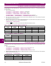
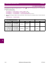
2. Measured values should be ±1.0 V. Apply the voltage values shown in the table and verify accuracy of the measured
values. View the measured values in:
A2 METERING DATA ÖØ VOLTAGE METERING
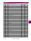
INJECTED CURRENT EXPECTED
CURRENT
MEASURED CURRENT
1 A UNIT 5 A UNIT PHASE A PHASE B PHASE C
0.1 A 0.5 A 100 A
0.2 A 1.0 A 200 A
0.5 A 2.5 A 500 A
1 A 5 A 1000 A
1.5 A 7.5 A 1500 A
2 A 10 A 2000 A
APPLIED LINE-
NEUTRAL VOLTAGE
EXPECTED VOLTAGE
READING
MEASURED VOLTAGE
A-N B-N C-N
30 V 300 V
50 V 500 V
100 V 1000 V
150 V 1500 V
200 V 2000 V
270 V 2700 V