


1-2 489 Generator Management Relay GE Multilin
1.1 OVERVIEW 1 INTRODUCTION
1
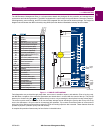
Power metering is a standard feature in the 489. The table below outlines the metered parameters available to the operator
or plant engineer either through the front panel or communications ports. The 489 is equipped with three fully functional and
independent communications ports. The front panel RS232 port may be used for setpoint programming, local interrogation
or control, and firmware upgrades. The computer RS485 port may be connected to a PLC, DCS, or PC based interface
software. The auxiliary RS485 port may be used for redundancy or simultaneous interrogation and/or control from a second
PLC, DCS, or PC program. There are also four 4 to 20 mA transducer outputs that may be assigned to any measured
parameter. The range of these outputs is scalable. Additional features are outlined below.
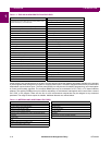
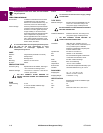
Table 1–1: TRIP AND ALARM PROTECTION FEATURES
TRIP PROTECTION ALARM PROTECTION
Seven (7) Assignable Digital Inputs: General Input,
Sequential Trip (low forward power or reverse power), Field-
Breaker discrepancy, and Tachometer
7 assignable digital inputs: general input and tachometer
Overload
Negative Sequence
Offline Overcurrent (protection during startup) Ground Overcurrent
Inadvertent Energization Ground Directional
Phase Overcurrent with Voltage Restraint Undervoltage
Negative-Sequence Overcurrent Overvoltage
Ground Overcurrent Volts Per Hertz
Percentage Phase Differential Underfrequency
Ground Directional Overfrequency
High-Set Phase Overcurrent Neutral Overvoltage (Fundamental)
Undervoltage Neutral Undervoltage (3rd Harmonic)
Overvoltage Reactive Power (kvar)
Volts Per Hertz Reverse Power
Voltage Phase Reversal Low Forward Power
Underfrequency (two step) RTD: Stator, Bearing, Ambient, Other
Overfrequency (two step) Short/Low RTD
Neutral Overvoltage (Fundamental) Open RTD
Neutral Undervoltage (3rd Harmonic) Thermal Overload
Loss of Excitation (2 impedance circles) Trip Counter
Distance Element (2 zones of protection) Breaker Failure
Reactive Power (kvar) for loss of field Trip Coil Monitor
Reverse Power for anti-motoring VT Fuse Failure
Low Forward Power Demand: Current, MW, Mvar, MVA
RTDs: Stator, Bearing, Ambient, Other Generator Running Hours
Thermal Overload Analog Inputs 1 to 4
Analog Inputs 1 to 4 Service (Self-Test Failure)
Electrical Lockout IRIG-B Failure
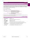
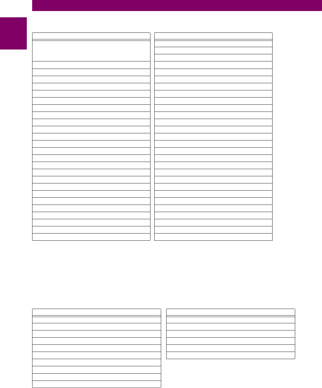
Table 1–2: METERING AND ADDITIONAL FEATURES
METERING ADDITIONAL FEATURES
Voltage (phasors) Drawout Case (for ease of maintenance and testing)
Current (phasors) and Amps Demand Breaker Failure
Real Power, MW Demand, MWh Trip Coil Supervision
Apparent Power and MVA Demand VT Fuse Failure
Reactive Power, Mvar Demand, Positive and Negative MVarh Simulation
Frequency Flash Memory for easy firmware upgrades
Power Factor
RTD
Speed in RPM with a Key Phasor Input
User-Programmable Analog Inputs