GE Multilin 489 Generator Management Relay A-1
APPENDIX A A.1 STATOR GROUND FAULT
A
APPENDIX A Application NotesA.1 Stator Ground Fault A.1.1 DESCRIPTION
This application note describes general protection concepts and provides guidelines on the use of the 489
to protect a generator stator against ground faults. Detailed connections for specific features must be
obtained from the relay manual. Users are also urged to review the material contained in the 489 manual on
each specific protection feature discussed here.
The 489 Generator Management Relay offers a number of elements to protect a generator against stator ground faults.
Inputs are provided for a neutral-point voltage signal and for a zero-sequence current signal. The zero-sequence current
input can be into a nominal 1 A secondary circuit or an input reserved for a special GE Multilin type HGF ground CT for very
sensitive ground current detection. Using the HGF CT allows measurement of ground current values as low as 0.25 A pri-
mary. With impedance-grounded generators, a single ground fault on the stator does not require that the unit be quickly
removed from service. The grounding impedance limits the fault current to a few amperes. A second ground fault can, how-
ever, result in significant damage to the unit. Thus the importance of detecting all ground faults, even those in the bottom
5% of the stator. The fault detection methods depend on the grounding arrangement, the availability of core balance CT,
and the size of the unit. With modern full-featured digital generator protection relays such as the 489, users do not incur
additional costs for extra protection elements as they are all part of the same device. This application note provides general
descriptions of each of the elements in the 489 suitable for stator ground protection, and discusses some special applica-
tions.
A.1.2 NEUTRAL OVERVOLTAGE ELEMENT
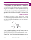
The simplest, and one of the oldest methods to detect stator ground faults on high-impedance-grounded generators, is to
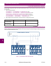
sense the voltage across the stator grounding resistor (See References [1, 2] at the end of this section). This is illustrated,
in a simplified form in the figure below. The voltage signal is connected to the V
neutral
input of the 489, terminals E10 and
F10. The V
neutral
signal is the input signal for the 489 neutral overvoltage protection element. This element has an alarm
and a trip function, with separately adjustable operate levels and time delays. The trip function offers a choice of timing
curves as well as a definite time delay. The neutral overvoltage function responds to fundamental frequency voltage at the
generator neutral. It provides ground fault protection for approximately 95% of the stator winding. The limiting factor is the
level of voltage signal available for a fault in the bottom 5% of the stator winding. The element has a range of adjustment,
for the operate levels, of 2 to 100 V.
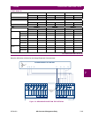
Figure A–1: STATOR GROUND FAULT PROTECTION
The operating time of this element should be coordinated with protective elements downstream, such as feeder ground
fault elements, since the neutral overvoltage element will respond to external ground faults if the generator is directly con-
nected to a power grid, without the use of a delta-wye transformer.
In addition, the time delay should be coordinated with the ground directional element (discussed later), if it is enabled, by
using a longer delay on the neutral overvoltage element than on the directional element.
It is recommended that an isolation transformer be used between the relay and the grounding impedance to reduce com-
mon mode voltage problems, particularly on installations requiring long leads between the relay and the grounding imped-
ance.
CAUTION
808739A1.CDR
Generator
R is selected for a
maximum fault current
of 10 A, typically.
Overvoltage
Relay
R
Distribution
Transformer


