


4 489 Generator Management Relay GE Multilin
INDEX
configuration.....................................................................3-7
installation........................................................................3-5
loading setpoints ...............................................................3-9
phasors..........................................................................3-15
printing setpoints/actual values .........................................3-11
requirements.....................................................................3-4
startup .............................................................................3-7
trending..........................................................................3-12
troubleshooting ...............................................................3-17
upgrade............................................................................3-5
upgrading firmware ............................................................3-8
upgrading setpoint files ....................................................3-10
SPECIFICATIONS..............................................................1-4
SPEED ............................................................................5-17
STARTER
information .....................................................................4-11
operations ......................................................................4-16
status ............................................................................4-14
STATOR GROUND FAULT PROTECTION.......................... A-1
STATUS LEDs ...................................................................3-1
T
TACHOMETER................................................. 1-5, 4-18, 5-17
TEMPERATURE...............................................................5-16
TEMPERATURE DISPLAY..................................................4-8
TERMINAL LAYOUT...........................................................2-5
TERMINAL LIST.................................................................2-6
TERMINAL LOCATIONS.....................................................2-5
TERMINAL SPECIFICATIONS ............................................1-5
TEST ANALOG OUTPUT..................................................4-81
TEST INPUT ....................................................................4-16
TEST OUTPUT RELAYS...................................................4-81
TESTS
differential current accuracy................................................7-4
ground current accuracy ............................................7-4, 7-13
list ...................................................................................7-1
negative-sequence current accuracy ....................................7-5
neutral current accuracy .....................................................7-4
neutral voltage accuracy............................................ 7-4, 7-13
output current accuracy ......................................................7-3
output relays.....................................................................7-8
overload curves.................................................................7-9
phase current accuracy ......................................................7-3
power measurement.........................................................7-10
production tests.................................................................1-8
reactive power ................................................................7-11
RTD accuracy ...................................................................7-6
secondary injection setup ...................................................7-2
voltage input accurcay........................................................7-3
voltage phase reversal .....................................................7-12
THERMAL CAPACITY USED ..............................................5-3
THERMAL ELEMENTS .....................................................4-68
THERMAL MODEL
machine cooling ..............................................................4-66
setpoints ........................................................................4-55
specifications....................................................................1-7
unbalance bias................................................................4-65
THERMAL RESET............................................................4-16
THIRD HARMONIC VOLTAGE ........................................... A-5
TIME ........................................................................ 4-9, 5-12
TIME OVERCURRENT CURVES ........................................B-1
TIMERS ...........................................................................5-22
TIMING ............................................................................. 6-2
TOC CHARACTERISTICS.................................................4-21
TOC CURVES ...................................................................B-1
TRACE MEMORY .............................................................. 6-9
TRENDING.......................................................................3-12
TRIP COIL MONITOR .......................................................4-70
TRIP COIL SUPERVISION .......................................... 1-4, 7-7
TRIP COUNTER ............................................. 4-11, 4-69, 5-20
TRIP PICKUPS.................................................................. 5-6
TRIP RELAY............................................................2-13, 4-20
TRIP TIME ON OVERLOAD, ESTIMATED........................... 5-3
TRIPS ............................................................................... 4-5
TYPE TESTS..................................................................... 1-8
TYPICAL WIRING DIAGRAM.............................................. 2-7
U
UNBALANCE BIAS ...........................................................4-65
UNDERFREQUENCY........................................................4-37
UNDERVOLTAGE......................................................1-6, 4-33
USER DEFINABLE MEMORY MAP..................................... 6-8
V
VIBRATION ......................................................................2-11
VOLTAGE DEPENDENT OVERLOAD CURVE....................4-61
VOLTAGE INPUTS
description ......................................................................2-11
specifications ................................................................... 1-4
testing ............................................................................. 7-3
VOLTAGE METERING ......................................................5-14
VOLTAGE RESTRAINED OVERCURRENT
setpoints.........................................................................4-26
testing ............................................................................7-16
VOLTAGE SENSING.........................................................4-12
VOLTS/HERTZ .................................................................4-35
VT FUSE FAILURE ...........................................................4-71
VT RATIO.........................................................................4-12
VTFF................................................................................4-71
VTs
open delta.......................................................................4-41
setpoints.........................................................................4-12
wye connected.................................................................4-41
W
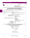
WARRANTY .............................................................. C-1, C-3
WAVEFORM CAPTURE ....................................3-14, 4-19, 6-9
WIRING DIAGRAM ............................................................ 2-8
WITHDRAWAL .................................................................. 2-3
WYE ................................................................................2-11
WYE CONNECTED VTs....................................................4-41