


GE Multilin 489 Generator Management Relay 6-47
6 COMMUNICATIONS 6.5 DNP POINT LISTS
6
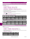
6.5.4 ANALOG INPUT / INPUT CHANGE (OBJECTS 30/32)
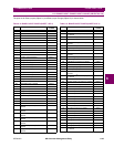
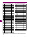
In the following table, the Format column indicates that the associated data point format is determined by the entry in Table
6–2: Data Formats on page 6–34. For example, an “F1” format is described in that table as a (16-bit) unsigned value with-
out any decimal places. Therefore, the value read should be interpreted in this manner. Many of the values reported by the
489 have a size of 32-bits and have had their upper and lower 16-bit components assigned to separate points. Where indi-
cated, refer to the appropriate note following the table for more detail.
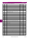
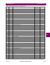
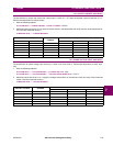
Table 6–8: ANALOG INPUTS POINT LIST (SHEET 1 OF 4)
INDEX FORMAT DESCRIPTION EVENT CLASS
ASSIGNED TO
NOTES
0 F133 Generator Status Class 1 Note 3
1 F1 Generator Thermal Capacity Used Class 1
2 F1 Estimated Trip Time On Overload (seconds, 65535 means never) Class 1
3 F134 Cause Of Last Trip Class 1 Note 3
4 F19 Time Of Last Trip (Upper 16 Bits) Class 1 Notes 3,4
5 F19 Time Of Last Trip (Lower 16 Bits) Class 1 Notes 3,4
6 F18 Date Of Last Trip (Upper 16 Bits) Class 1 Notes 3,4
7 F18 Date Of Last Trip (Lower 16 Bits) Class 1 Notes 3,4
8 F1 Tachometer Pre-Trip Class 1 Note 3
9 F1 Scale factor for pre-trip current readings (pre-trip points marked with
“Note 6”). Will always be a power of 10 (1, 10, 100, etc.). Changes only
when the configuration setpoints are changed.
Class 1 Note 3
10 F1 Phase A Pre-Trip Current Class 1 Notes 3, 6
11 F1 Phase B Pre-Trip Current Class 1 Notes 3, 6
12 F1 Phase C Pre-Trip Current Class 1 Notes 3, 6
13 F1 Phase A Pre-Trip Differential Current Class 1 Notes 3, 6
14 F1 Phase B Pre-Trip Differential Current Class 1 Notes 3, 6
15 F1 Phase C Pre-Trip Differential Current Class 1 Notes 3, 6
16 F1 Pre-Trip Negative Sequence Current Class 1 Note 3
17 F1 Ground Current Scale Factor. Will always be a power of 10 (1, 10, 100,
etc.). Changes only when the configuration setpoints are changed.
Class 1 Note 3
18 F6 Pre-Trip Ground Current (scaled according to previous setpoint) Class 1 Note 3
19 F1 Phase A-B Pre-Trip Voltage Class 1 Note 3
20 F1 Phase B-C Pre-Trip Voltage Class 1 Note 3
21 F1 Phase C-A Pre-Trip Voltage Class 1 Note 3
22 F3 Pre-Trip Frequency Class 1 Note 3
23 F1 Pre-Trip Real Power (MW) Class 1 Notes 3,8
24 F1 Pre-Trip Real Power (kW) Class 1 Notes 3,8
25 F1 Pre-Trip Reactive Power (Mar Class 1 Notes 3,8
26 F1 Pre-Trip Reactive Power (kvar) Class 1 Notes 3,8
27 F1 Pre-Trip Apparent Power (MVA) Class 1 Notes 3,8
28 F1 Pre-Trip Apparent Power (kVA) Class 1 Notes 3,8
29 F1 Last Trip Stator RTD Class 1 Note 3
30 F4 Last Trip Hottest Stator RTD Temperature (°C) Class 1 Note 3
31 F1 Last Trip Bearing RTD Class 1 Note 3
32 F4 Last Trip Hottest Bearing RTD Temperature (°C) Class 1 Note 3
33 F1 Last Trip Other RTD Class 1 Note 3
34 F4 Last Trip Hottest Other RTD Temperature (°C) Class 1 Note 3
35 F1 Last Trip Ambient RTD Class 1 Note 3
36 F4 Last Trip Hottest Ambient RTD Temperature (°C) Class 1 Note 3
37 F12 Pre-Trip Analog Input 1 Class 1 Notes 3,9