


4-80 489 Generator Management Relay GE Multilin
4.13 S12 TESTING 4 SETPOINTS
4
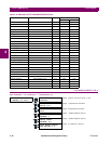
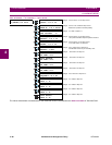
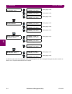
4.13.3 FAULT SETUP
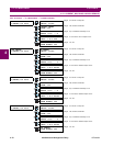
PATH: SETPOINTS ÖØ S12 TESTING ÖØ FAULT SETUP
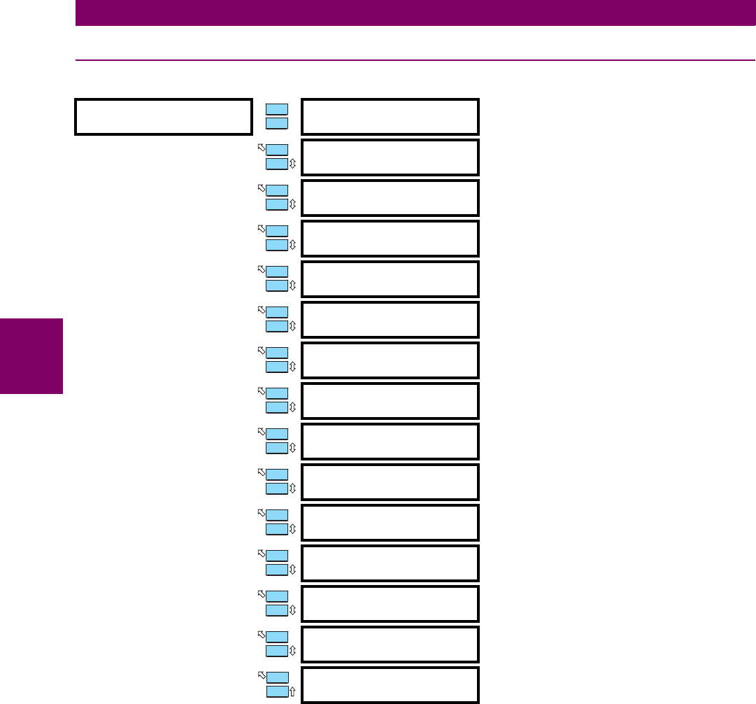
The values entered here are substituted for the measured values in the 489 when the SIMULATION MODE is "Simulate Fault".
FAULT SETUP
[ENTER] for more
FAULT Iphase
OUTPUT: 0.00 x CT
Range: 0.00 to 20.00 × CT in steps of 0.01
FAULT VOLTAGES
PHASE-N: 1.00 x Rated
Range: 0.00 to 1.50 × Rated in steps of 0.01
Entered as a phase-to-neutral quantity.
FAULT CURRENT
LAGS VOLTAGE: 0°
Range: 0 to 359° in steps of 1
FAULT Iphase
NEUTRAL: 0.00 x CT
Range: 0.00 to 20.00 × CT in steps of 0.01
180° phase shift with respect to Iphase OUTPUT
FAULT CURRENT
GROUND: 0.00 x CT
Range: 0.00 to 20.00 × CT in steps of 0.01
CT is either XXX:1 or 50:0.025
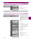
FAULT VOLTAGE
NEUTRAL: 0 Vsec
Range: 0.0 to 100.0 Vsec in steps of 0.1
Fundamental value only in secondary volts
FAULT STATOR
RTD TEMP: 40°C
Range: –50 to 250°C in steps of 1
FAULT BEARING
RTD TEMP: 40°C
Range: –50 to 250°C in steps of 1
FAULT OTHER
RTD TEMP: 40°C
Range: –50 to 250°C in steps of 1
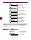
FAULT AMBIENT
RTD TEMP: 40°C
Range: –50 to 250°C in steps of 1
FAULT SYSTEM
FREQUENCY: 60.0 Hz
Range: 5.0 to 90.0 Hz in steps of 0.1
FAULT ANALOG
INPUT 1: 0%
Range: 0 to 100% in steps of 1
FAULT ANALOG
INPUT 2: 0%
Range: 0 to 100% in steps of 1
FAULT ANALOG
INPUT 3: 0%
Range: 0 to 100% in steps of 1
FAULT ANALOG
INPUT 4: 0%
Range: 0 to 100% in steps of 1
ENTER
ESCAPE
ð
ð
MESSAGE
ESCAPE
MESSAGE
ESCAPE
MESSAGE
ESCAPE
MESSAGE
ESCAPE
MESSAGE
ESCAPE
MESSAGE
ESCAPE
MESSAGE
ESCAPE
MESSAGE
ESCAPE
MESSAGE
ESCAPE
MESSAGE
ESCAPE
MESSAGE
ESCAPE
MESSAGE
ESCAPE
MESSAGE
ESCAPE
MESSAGE
ESCAPE