


GE Multilin 489 Generator Management Relay 1
TABLE OF CONTENTS
1. INTRODUCTION 1.1 OVERVIEW
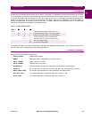
1.1.1 Description.........................................................................................................1-1
1.1.2 Ordering.............................................................................................................1-3
1.1.3 Other Accessories..............................................................................................1-3
1.2 SPECIFICATIONS
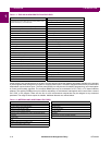
1.2.1 489 Specifications.............................................................................................. 1-4
2. INSTALLATION 2.1 MECHANICAL
2.1.1 Description.........................................................................................................2-1
2.1.2 Product Identification.......................................................................................... 2-2
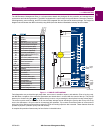
2.1.3 Installation.......................................................................................................... 2-3
2.1.4 Unit Withdrawal and Insertion ............................................................................2-3
2.1.5 Terminal Locations.............................................................................................2-5
2.2 ELECTRICAL
2.2.1 Typical Wiring Diagram......................................................................................2-7
2.2.2 General Wiring Considerations ..........................................................................2-8
2.2.3 Control Power .................................................................................................... 2-9
2.2.4 Current Inputs ....................................................................................................2-9
2.2.5 Voltage Inputs ..................................................................................................2-11
2.2.6 Digital Inputs ....................................................................................................2-11
2.2.7 Analog Inputs...................................................................................................2-11
2.2.8 Analog Outputs ................................................................................................2-12
2.2.9 RTD Sensor Connections ................................................................................ 2-12
2.2.10 Output Relays ..................................................................................................2-13
2.2.11 IRIG-B .............................................................................................................. 2-13
2.2.12 RS485 Communications Ports.........................................................................2-14
2.2.13 Dielectric Strength............................................................................................2-15
3. USER INTERFACES 3.1 FACEPLATE INTERFACE
3.1.1 Display ............................................................................................................... 3-1
3.1.2 LED Indicators....................................................................................................3-1
3.1.3 RS232 Program Port.......................................................................................... 3-2
3.1.4 Keypad............................................................................................................... 3-2
3.2 SOFTWARE INTERFACE
3.2.1 Requirements..................................................................................................... 3-4
3.2.2 Installation/Upgrade ........................................................................................... 3-5
3.2.3 Configuration...................................................................................................... 3-7
3.2.4 Using 489PC...................................................................................................... 3-8
3.2.5 Trending........................................................................................................... 3-12
3.2.6 Waveform Capture...........................................................................................3-14
3.2.7 Phasors............................................................................................................ 3-15
3.2.8 Event Recorder ................................................................................................ 3-16
3.2.9 Troubleshooting ...............................................................................................3-17
4. SETPOINTS 4.1 OVERVIEW
4.1.1 Setpoint Message Map ...................................................................................... 4-1
4.1.2 Trips / Alarms/ Control Features ........................................................................4-5
4.1.3 Relay Assignment Practices .............................................................................. 4-5
4.1.4 Dual Setpoints....................................................................................................4-6
4.1.5 Commissioning...................................................................................................4-6
4.2 S1 489 SETUP
4.2.1 Passcode ........................................................................................................... 4-7
4.2.2 Preferences........................................................................................................4-7
4.2.3 Serial Ports......................................................................................................... 4-8
4.2.4 Real Time Clock................................................................................................. 4-9
4.2.5 Default Messages .............................................................................................. 4-9