


4-12 489 Generator Management Relay GE Multilin
4.3 S2 SYSTEM SETUP 4 SETPOINTS
4
4.3S2 SYSTEM SETUP 4.3.1 CURRENT SENSING
PATH: SETPOINTS ÖØ S2 SYSTEM SETUP Ö CURRENT SENSING
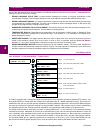
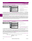
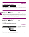
As a safeguard, the PHASE CT PRIMARY and GENERATOR PARAMETERS setpoints are defaulted to "--------" when shipped,
indicating that the 489 was never programmed. Once these values are entered, the 489 will be in service. Select the Phase
CT so that the maximum fault current does not exceed 20 times the primary rating. When relaying class CTs are pur-
chased, this precaution helps prevent CT saturation under fault conditions. The secondary value of 1 or 5 A must be spec-
ified when ordering so the proper hardware will be installed. The
PHASE CT PRIMARY setpoint applies to both the neutral end
CTs as well as the output CTs.
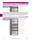
For high resistance grounded systems, sensitive ground current detection is possible if the 50:0.025 Ground CT is used. To
use the 50:0.025 CT input, set GROUND CT to "50:0.025". No additional ground CT messages will appear. On solid or low
resistance grounded systems, where fault currents may be quite large, the 489 1 A/5 A secondary Ground CT input should
be used. Select the Ground CT primary so that potential fault current does not exceed 20 times the primary rating. When
relaying class CTs are purchased, this precaution will ensure that the Ground CT does not saturate under fault conditions.
The 489 uses a nominal CT primary rating of 5 A for calculation of pickup levels.
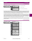
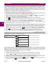
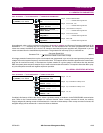
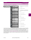
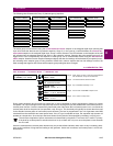
4.3.2 VOLTAGE SENSING
PATH: SETPOINTS ÖØ S2 SYSTEM SETUP ÖØ VOLTAGE SENSING
The voltage transformer connections and turns ratio are entered here. The VT should be selected such that the secondary
phase-phase voltage of the VTs is between 70.0 and 135.0 V when the primary is at generator rated voltage.
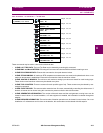
The Neutral VT ratio must be entered here for voltage measurement across the neutral grounding device. Note that the
neutral VT input is not intended to be used at continuous voltages greater than 240 V. If the voltage across the neutral input
is less than 240 V during fault conditions, an auxiliary voltage transformer is not required. If this is not the case, use an aux-
iliary VT to drop the fault voltage below 240 V. The
NEUTRAL VT RATIO entered must be the total effective ratio of the
grounding transformer and any auxiliary step up or step down VT.
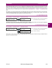
For example, if the distribution transformer ratio is 13200:480 and the auxiliary VT ratio is 600:120, the
NEUTRAL VT RATIO
setpoint is calculated as:
(EQ 4.1)
Therefore, set NEUTRAL VT RATIO to 137.50:1
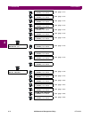
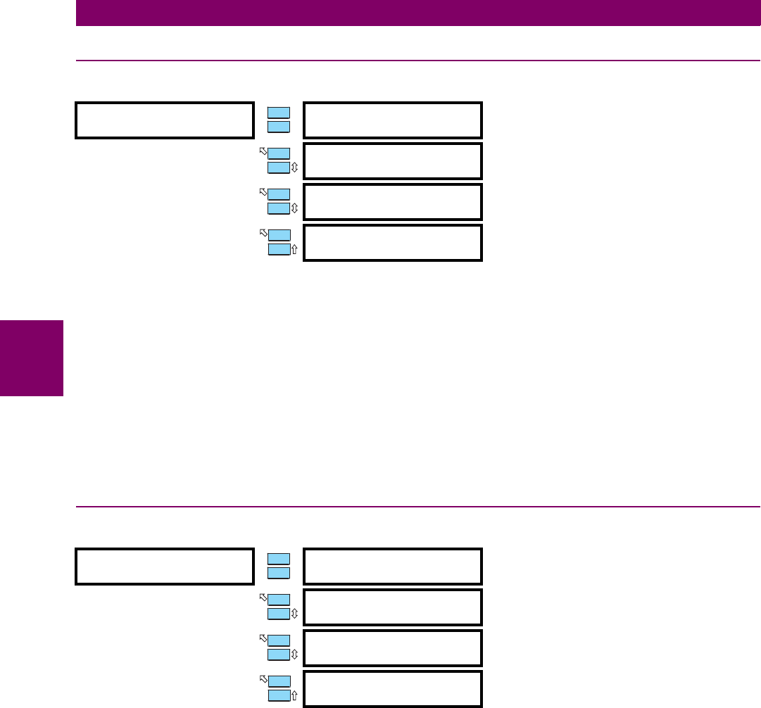
CURRENT SENSING
[ENTER] for more
PHASE CT PRIMARY:
-------------
Range: 1 to 5000 step 1, Not Programmed
GROUND CT:
50:0.025
Range: None, 1A Secondary, 5A Secondary, 50:0.025
GROUND CT RATIO:
100: 1
Range: 10 to 10000 in steps of 1
Message seen only if Ground CT Type is 1 A
GROUND CT RATIO:
100: 5
Range: 10 to 10000 in steps of 1
Message seen only if Ground CT Type is 5 A
VOLTAGE SENSING
[ENTER] for more
VT CONNECTION TYPE:
None
Range: Open Delta, Wye, None
VOLTAGE TRANSFORMER
RATIO: 5.00:1
Range: 1.00:1 to 300.00:1 in steps of 0.01
NEUTRAL VOLTAGE
TRANSFORMER: No
Range: No, Yes
NEUTRAL VT
RATIO: 5.00:1
Range: 1.00:1 to 240.00:1 in steps of 0.01. Seen only if
NEUTRAL VOLTAGE TRANSFORMER is "Yes"
ENTER
ESCAPE
ð
ð
MESSAGE
ESCAPE
MESSAGE
ESCAPE
MESSAGE
ESCAPE
ENTER
ESCAPE
ð
ð
MESSAGE
ESCAPE
MESSAGE
ESCAPE
MESSAGE
ESCAPE
NEUTRAL VT RATIO Distribution Transformer Ratio Auxiliary VT Ratio× : 1=
13200
480
----------------
600
120
--------- -
× : 1 137.50 : 1==