


GE Multilin 489 Generator Management Relay 3-1
3 USER INTERFACES 3.1 FACEPLATE INTERFACE
3
3 USER INTERFACES 3.1FACEPLATE INTERFACE 3.1.1 DISPLAY
All messages appear on a 40-character liquid crystal display. Messages are in plain English and do not require the aid of an
instruction manual for deciphering. When the user interface is not being used, the display defaults to the user-defined sta-
tus messages. Any trip or alarm automatically overrides the default messages and is immediately displayed.
3.1.2 LED INDICATORS
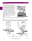
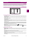
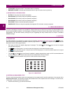
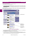
Figure 3–1: 489 LED INDICATORS
a) 489 STATUS LED INDICATORS
• 489 IN SERVICE: Indicates that control power is applied, all monitored input/output and internal systems are OK, the
489 has been programmed, and is in protection mode, not simulation mode. When in simulation or testing mode, the
LED indicator will flash.
• SETPOINT ACCESS: Indicates that the access jumper is installed and passcode protection has been satisfied. Set-
points may be altered and stored.
• COMPUTER RS232: Flashes when there is any activity on the RS232 communications port. Remains on continuously
if incoming data is valid.
• COMPUTER RS485 / AUXILIARY RS485: Flashes when there is any activity on the computer/auxiliary RS485 com-
munications port. These LEDs remains on continuously if incoming data is valid and intended for the slave address
programmed in the relay.
• ALT. SETPOINTS: Flashes when the alternate setpoint group is being edited and the primary setpoint group is active.
Remains on continuously if the alternate setpoint group is active. The alternate setpoint group feature is enabled as
one of the assignable digital inputs. The alternate setpoints group can be selected by setting the
S3 DIGITAL INPUTS /
DUAL SETPOINTS / ACTIVATE SETPOINT GROUP setpoint to "Group 2".
• RESET POSSIBLE: A trip or latched alarm may be reset. Pressing the key clears the trip/alarm.
• MESSAGE: Indicator flashes when a trip or alarm occurs. Press the key to scroll through the diagnostic mes-
sages. Remains solid when setpoint and actual value messages are being viewed. Pressing the key returns the
display to the default messages.
b) GENERATOR STATUS LED INDICATORS
• BREAKER OPEN: Uses the breaker status input signal to indicate that the breaker is open and the generator is offline.
• BREAKER CLOSED: Uses the breaker status input signal to indicate that the breaker is closed and the generator is
online.
• HOT STATOR: Indicates that the generator stator is above normal temperature when one of the stator RTD alarm or
trip elements is picked up or the thermal capacity alarm element is picked up.
• NEG. SEQUENCE: Indicates that the negative sequence current alarm or trip element is picked up.
• GROUND: Indicates that at least one of the ground overcurrent, neutral overvoltage (fundamental), or neutral under-
voltage (3rd harmonic) alarm/trip elements is picked up.
• LOSS OF FIELD: Indicates that at least one of the reactive power (kvar) or field-breaker discrepancy alarm/trip ele-
ments is picked up.
808732A1.CDR
489 STATUS GENERATOR STATUS OUTPUTRELAYS
R1TRIP
R2AUXILIARY
R3AUXILIARY
R4AUXILIARY
R5ALARM
R6SERVICE
BREAKEROPEN
BREAKERCLOSED
HOTSTATOR
NEG.SEQUENCE
GROUND
LOSSOFFIELD
VTFAILURE
BREAKERFAILURE
489INSERVICE
SETPOINTACCESS
COMPUTERRS232
COMPUTERRS485
AUXILIARYRS485
ALT.SETPOINTS
RESET
POSSIBLE
MESSAGE
RESET
NEXT
NEXT