


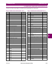
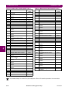
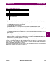
6-38 489 Generator Management Relay GE Multilin
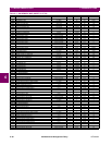
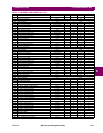
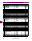
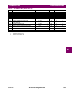
6.3 MODBUS MEMORY MAP 6 COMMUNICATIONS
6
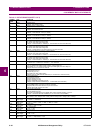
F211 Unsigned
16 bit integer
Volts/Hertz element type
0 = Curve #1, 1 = Curve #2, 2 = Curve #2, 3 = Definite Time
F212 Unsigned
16 bit integer
RTD number
F213 Unsigned
16 bit integer
Communications monitor port selection
0 = Computer RS485, 1 = Auxiliary RS485, 2 = Front Panel RS232
F214 Unsigned 16 bit
integer
Waveform Memory Channel Selector
F215 Unsigned
16 bit integer
Current Source
0 = Neutral-end CTs; 1 = Output-end CTs
F216 Unsigned
16 bit integer
DNP Port Selection
0 = None, 1 = Computer RS485, 2 = Auxiliary RS485, 3 = Front Panel RS485
F217 Unsigned
16 bit integer
Ground Directional MTA
0 = 0°, 1 = 90°, 2 = 180°, 3 = 270°
F218 Unsigned
16 bit integer
Breaker State
0 = 52 Closed, 1 = 52 Open/Closed
F219 Unsigned
16 bit integer
Step Up Transformer Type
0 = None, 1 = Delta/Wye
F220 Unsigned
16 bit integer
IRIG-B Type
0 = None, 1 = DC Shift, 2 = Amplitude Modulated
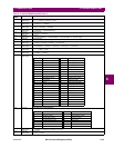
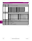
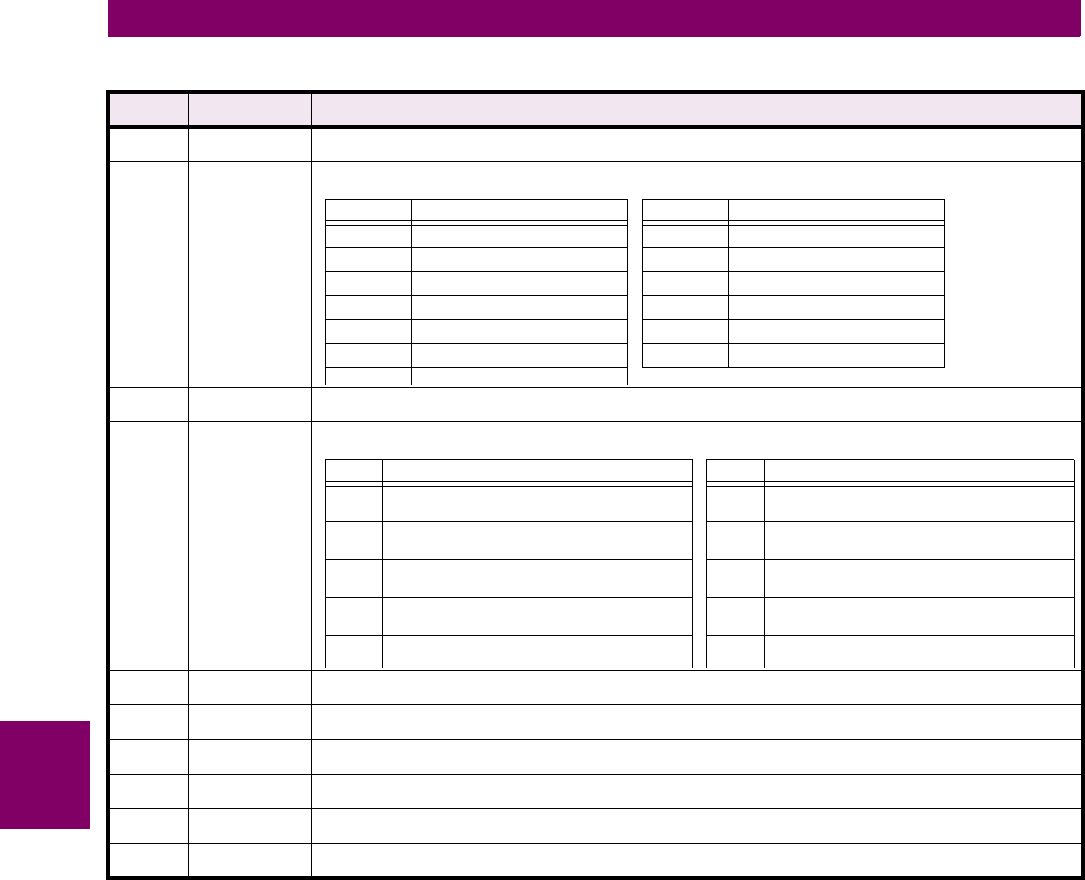
Table 6–2: DATA FORMATS (SHEET 5 OF 5)
FORMAT
CODE
TYPE DEFINITION
VALUE PARAMETER VALUE PARAMETER
0All 7RTD #7
1RTD #1 8RTD #8
2RTD #2 9RTD #9
3 RTD #3 10 RTD #10
4 RTD #4 11 RTD #11
5 RTD #5 12 RTD #12
6RTD #6
VALUE PARAMETER VALUE PARAMETER
0 Phase A line current
512 counts = 1 × CT
5 Neutral-end phase C line current
512 counts = 1 × CT
1 Phase B line current
512 counts = 1 × CT
6 Ground current
512 counts = 1 × CT
2 Phase C line current
512 counts = 1 × CT
7 Phase A to neutral voltage
3500 counts = 120 secondary volts
3 Neutral-end phase A line current
512 counts = 1 × CT
8 Phase B to neutral voltage
3500 counts = 120 secondary volts
4 Neutral-end phase B line current
512 counts equals 1 × CT
9 Phase C to neutral voltage
3500 counts = 120 secondary volts