4-6 489 Generator Management Relay GE Multilin
4.1 OVERVIEW 4 SETPOINTS
4
4.1.4 DUAL SETPOINTS
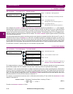
The 489 has dual settings for the current, voltage, power, RTD, and thermal model protection elements (setpoints pages S5
to S9). These setpoints are organized in two groups: the main group (Group 1) and the alternate group (Group 2). Only one
group of settings is active in the protection scheme at a time. The active group can be selected using the
ACTIVATE SET-
POINT GROUP setpoint or an assigned digital input in the S3 Digital Inputs setpoints page. The LED indicator on the face-
plate of the 489 will indicate when the alternate setpoints are active in the protection scheme. Independently, the setpoints
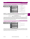
in either group can be viewed and/or edited using the
EDIT SETPOINT GROUP setpoint. Headers for each setpoint message
subgroup that has dual settings will be denoted by a superscript number indicating which setpoint group is being viewed or
edited. Also, when a setpoint that has dual settings is stored, the flash message that appears will indicate which setpoint
group setting has been changed.
If only one setting group is required, edit and activate only Group 1 (that is, do not assign a digital input to Dual Setpoints,
and do not alter the
ACTIVATE SETPOINT GROUP setpoint or EDIT SETPOINT GROUP setpoint in S3 DIGITAL INPUTS).
4.1.5 COMMISSIONING
Tables for recording of 489 programmed setpoints are available as a Microsoft Word document from the GE Multilin website
at http://www.GEindustrial.com/multilin
. See the Support Documents section of the 489 Generator Management Relay
page for the latest version. This document is also available in print from the GE Multilin literature department (request pub-
lication number GET-8445).


