


2-8 489 Generator Management Relay GE Multilin
2.2 ELECTRICAL 2 INSTALLATION
2
2.2.2 GENERAL WIRING CONSIDERATIONS
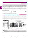
A broad range of applications are available to the user and it is not possible to present typical connections for all possible
schemes. The information in this section will cover the important aspects of interconnections, in the general areas of instru-
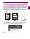
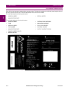
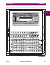
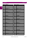
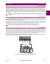
ment transformer inputs, other inputs, outputs, communications and grounding. See Figure 2–8: Terminal Layout and Table
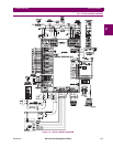
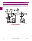
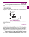
2–1: 489 Terminal List for terminal arrangement, and Figure 2–9: Typical Wiring Diagram for typical connections.
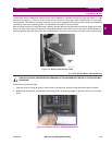
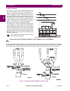
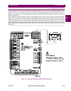
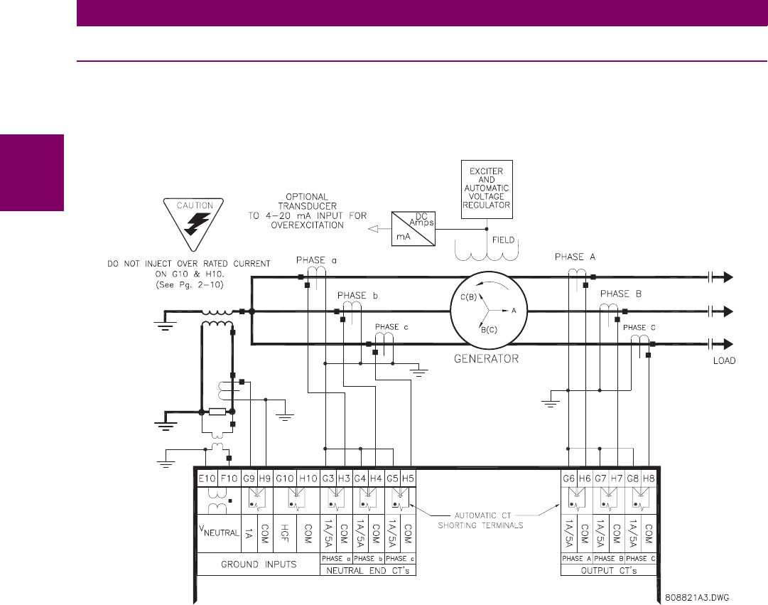
Figure 2–10: TYPICAL WIRING (DETAIL)