S205 Skid-Steer Loader
Operation & Maintenance Manual 40
ATTACHMENTS (CONT’D)
Installing And Removing The Attachment (Hand
Lever Bob-Tach) (Cont’d)
Installing (Cont’d)
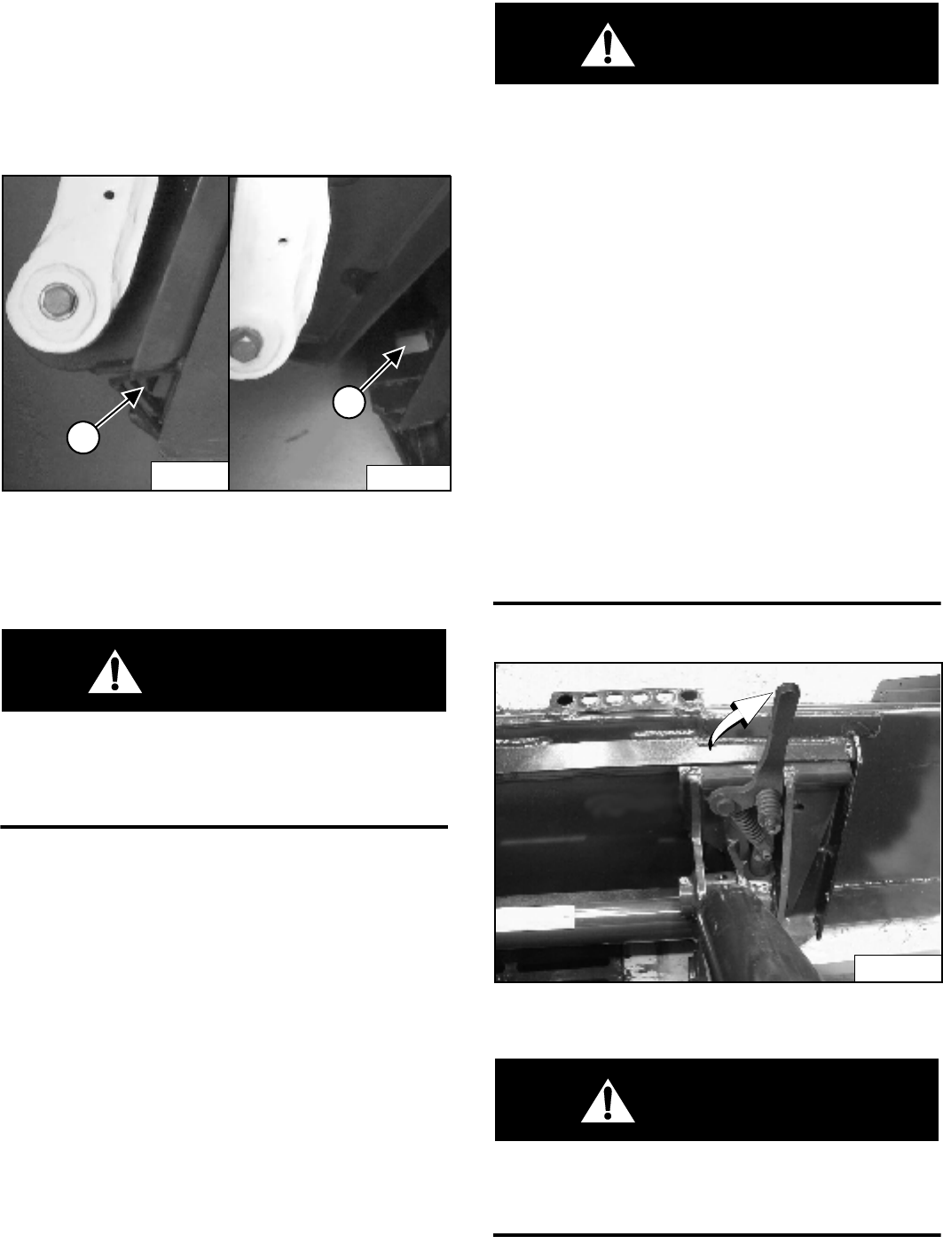
Figure 81
The wedges (1) [Figure 81] must extend through the
holes (2) [Figure 81] in the mounting frame of the bucket
(or attachment), securely fastening the bucket to the
Bob-Tach.
WARNING
Bob-Tach wedges must extend through the holes in
attachment. Levers must be fully down and locked.
Failure to secure wedges can allow attachment to
come off and cause injury or death.
W-2102-0588
Removing
Lower the lift arms and put the attachment flat on the
ground and lower or close the hydraulic equipment.
• If the attachment is hydraulically controlled
(combination bucket, backhoe, etc.), stop the engine
and relieve hydraulic pressure at the quick couplers.
(See Relieve Hydraulic Pressure (Loader and
Attachment) on Page 23.)
Raise the seat bar, unfasten the seat belt, set the parking
brake and exit the loader.
WARNING
Before you leave the operator’s seat:
• Lower the lift arms, put the attachment flat on the
ground.
• Stop the engine.
• Engage the parking brake.
• Raise seat bar.
• (Foot Pedal Controls) Move pedals until both
lock.
• (Advanced Control system - ACS) Move the
hydraulic controls to the NEUTRAL POSITION to
make sure that both lift and tilt functions are
deactivated.
The seat bar system must deactivate the lift and
tilt control functions when the seat bar is up.
Service the system if hand controls do not
deactivate.
• (Selectable Joystick Controls - SJC) Move the
joysticks to the NEUTRAL POSITION to make
sure that travel and hydraulic functions are
deactivated.
The seat bar system must deactivate these
functions when the seat bar is up. Service the
system if controls do not deactivate.
W-2463-0603
Figure 82
Pull the Bob-Tach levers [Figure 82] all the way up.
WARNING
Bob-Tach levers have spring tension. Hold lever
tightly and release slowly. Failure to obey warning
can cause injury.
W-2054-1285
N-16043A
1
N-16044A
2
P-31693A


