


S205 Skid-Steer Loader
Operation & Maintenance Manual 84
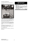
ELECTRICAL SYSTEM
Description
Figure 150
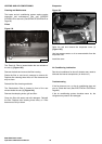
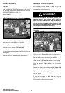
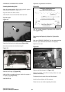
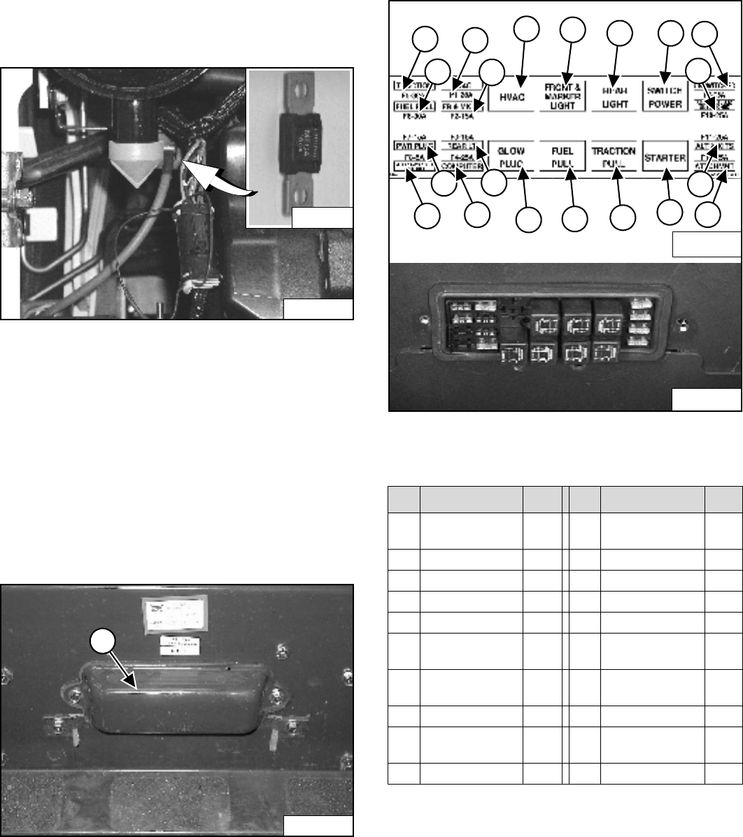
The loader has a 12 volt, negative ground alternator
charging system. The electrical system is protected by
fuses located in the cab on the steering control panel and
a 100 amp. master fuse [Figure 150] in the engine
compartment on the left side of the engine. The fuses will
protect the electrical system when there is an electrical
overload. The reason for the overload must be found
before starting the engine again.
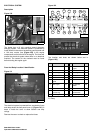
Fuse And Relay Location / Identification
Figure 151
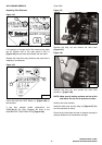
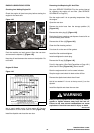
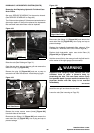
The electrical system is protected from overload by fuses
and relays under the fuse panel cover (1) [Figure 151]. A
decal is inside the cover to show location and amp
ratings.
Remove the cover to check or replace the fuses.
Figure 152
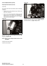
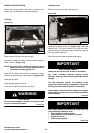
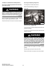
The location and sizes are shown below and in
[Figure 152].
R - Relay
P-24651
P-13849
P-26323
1
REF DESCRIPTION AMP REF DESCRIPTION AMP
1 Traction 30 11 Front & Marker
Lights
R
2 Fuel Shutoff 30 12 Fuel Shutoff R
3 Power Plug - - 13 Rear Lights R
4 ACS/AWS/SJC - - 14 Trac ti on R
5 Heater 25 15 Switch Power R
6 Front & Marker
Lights
15 16 Starter R
7 Rear Lights 15 17 Unswitched
Attach.
25
8 Bobcat Controller 25 18 Switched Attach. 25
9 Heater & Air
Conditioning
- - 19 Alternator &
Accessories
25
10 Glow Plugs R 20 Accessory Plug 25
7117407
1
2
5
6
9
17
11
13
15
4
3
8
7
10
20
19
12
14
16
18
N-19660