


Groundsmaster 5900/5910 Hydraulic SystemPage 4 -- 23
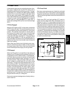
PTO Mow Circuit
A three section gear pump is coupled to the piston (trac-
tion) pump. Hydraulic flow for the PTO mow circuit is
supplied by two (2) sections of the gear pump. The gear
pump section (P1) closest to the piston pump supplies
hydraulic flow in series to the right and left decks, while
the next gear pump section (P2) supplies the center
deck. Each of the three (3) cutting decks is controlled by
a hydraulic control manifold equipped with a solenoid
control valve (S), logic cartridges (LC1) and (LC2), a
brake relief cartridge (RV2) and a circuit relief cartridge
(RV1).
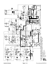
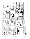
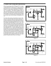
PTO Not Engaged
When the PTO switch is OFF or if the deck is raised with
thePTOswitch ON, thePTOmanifold solenoid valve (S)
is not energized and the solenoid spool is in the neutral
position. The solenoid valve spool in neutral allows a
small amount of hydraulic flow to return to tank through
a manifold sensing line w hich causes a pressure in-
crease that shifts logic cartridge LC1. The pump flow is
routed through shifted LC1 and out manifold port P2.
Logic cartridge LC2 remains in the unshifted position to
prevent any return flow from the deck motor to keep the
motor from rotating.
Return flow from the front and right deck control man-
ifolds is routed through the oil cooler, oil filter and then
to the gear pump input. Return flow from the left deck
control manifold provides supply for the right deck.
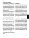
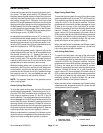
PTO Engaged
When the PTO switch is turned ON and the decks are
lowered, the PTO control manifold solenoid valve (S) is
energized by the TEC--5002 controller. The shiftedsole-
noid valve spool prevents any sense line flow through
the spool which causes the logic cartridge LC1 to be in
its neutral position. Gear pump flow entering the man-
ifold is routed out manifold port M1 and to the cutting
deck motor. The return flow from the deck motor re--en-
ters manifold port M2. The shifted solenoid valve spool
allows a small amount of hydraulic flow to return to tank
through a manifold sensing line which causes a pres-
sure increase that shifts logic cartridge LC2. Hydraulic
flow is routed through shifted LC2, out manifold port P2,
through the oil cooler and filter and then is routed to the
gear pump input. The deck motor continues to rotate as
long as solenoid valve (S) is energized.
Deckmotorcasedrainleakagereturnsdirectlyto the hy-
draulic reservoir.
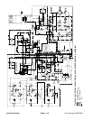
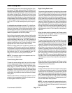
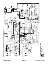
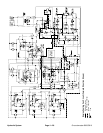
PTO Circuit Relief
Maximum mow circuit pressure is limited for each deck
by a relief valve (RV1) in the hydraulic control manifold.
The center andleft deck reliefvalves are setat 3000 PSI
(207bar)andtherightdeck relief valve is set at 2000 PSI
(138 bar).
Relief valve (RV1) and logic cartridge (LC1) work to-
gether as a two stage relief. When increased circuit re-
sistance is met or if a cutting blade should s trike an
object, the pressure increase is felt at the relief valve. If
the pressure should exceed the relief valve setting, the
relief valve willopen, creating asmall amount ofhydrau-
lic flow to return to tank through a manifold sensing line.
This flow causes a pressure increase that shifts logic
cartridgeLC1anddivertscircuitflow away from the deck
motor to manifold port P2 (Fig. 12). When circuit pres-
surelowers,relief valve(RV1)closeswhichreturnslogic
cartridge LC1 back to its neutral position allowing flow
to return to the deck motor.
Figure 12
PUMPFLOW
RETURN
SOLENOID SENERGIZED
RV1SHIFTED
LC1SHIFTED
DECK MOTORSTALLED
Hydraulic
System