


Groundsmaster 5900/5910Hydraulic System Page 4 -- 128
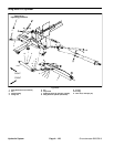
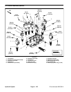
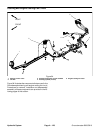
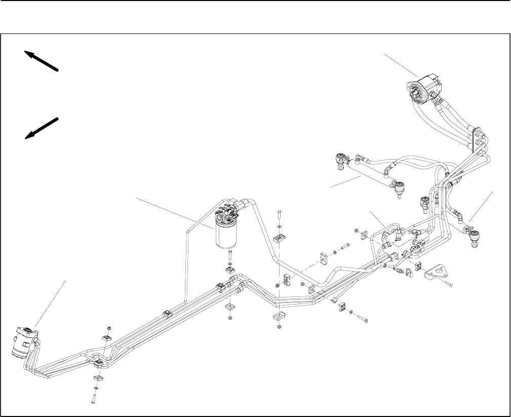
Steering and Engine Cooling Fan Circuit
1. Steering control valve
2. Oil filter
3. Steering/cooling fan control manifold
4. Steering cylinder (2 used)
5. Engine cooling fan motor
Figure 94
FRONT
RIGHT
2
1
3
4
5
4
Figure 94 illustrates thecomponents that are used inthe
Groundsmaster steering and engine cooling fan circuit.
Procedures for removal, installation and disassembly/
assembly of these components are provided in the fol-
lowing pages of this section.