


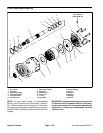


Groundsmaster 5900/5910Hydraulic System Page 4 -- 88
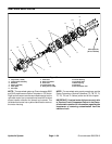
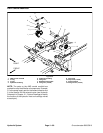
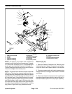
Traction Control Manifold Service
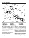
20 ft--lb
(27 N--m)
75 ft--lb
(101 N--m)
5 ft--lb
(6.7 N--m)
50 ft--lb
(67 N--m)
6
7
12
13
10
8
2
3
1
11
9
14
15
16
4
5
3
6
7
20 ft--lb
(27 N--m)
20 ft--lb
(27 N--m)
20 ft--lb
(27 N--m)
20 ft--lb
(27 N--m)
75 ft--lb
(101 N--m)
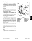
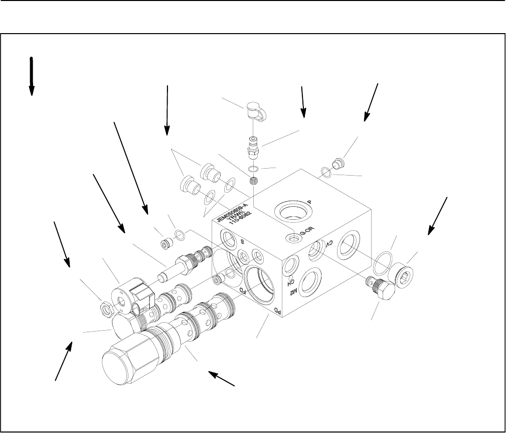
1. Dust cap
2. Quick fitting (G--OR)
3. O--ring
4. Orifice (G--OR)
5. #8 NWD plug
6. O--ring
7. #4 NWD plug (3 used)
8. Solenoid valve (S)
9. Solenoid coil
10. Nut
11. Flow divider (FD)
12. Pilot directional valve (PD)
13. Manifold body
14. Check valve (CV)
15. #12 NWD plug
16. O--ring
Figure 63
UP
NOTE: The ports on the traction control manifold are
marked for easy identification ofcomponents. Example:
P is the piston pump connection port and S is the loca-
tion for the solenoid valve (see Hydraulic Schematic in
Chapter 10 -- Foldout Drawings to identify the function
of the hydraulic lines and cartridge valves at each port).
NOTE: The traction control manifold includes several
zero leak NWD plugs. These plugs have a tapered seal-
ing surface on the plug head that is designed to resist
vibration induced plug loosening. The zero leak plugs
also have an O--ring as a s econdary seal. If zero leak
plug removal is necessary, lightly rap the plug head us-
ing a punch and hammer before using an allen wrench
toremovetheplug:the impact will allowplugremovalwi-
th less chance of damageto the socket head of the plug.
When installing plugs, refer to Figure 63forpluginstalla-
tion torque.