


Groundsmaster 5900/5910Page 5 -- 64Electrical System
Battery Service
The batteries are the heartof the electrical system. With
regular and properservice, battery lifecan be extended.
Additionally, battery and electrical component failure
can be prevented.
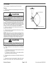
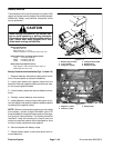
CAUTION
When working with batteries, use extreme cau-
tion to avoid splashing or spilling electrolyte.
Electrolyte can destroy clothing andburn skin or
eyes. Always wear safety goggles and a face
shield when working with batteries.
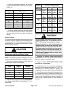
Battery Specifications
BCI Group Size 34
690 CCA at 0
o
F (--17.8
o
C)
Reserve Capacity of 110 minutes at 80
o
F (26.7
o
C)
Battery Dimensions (including terminal posts)
Length 10.2 inches (259 mm)
Width 6.6 inches (168 mm)
Height 8.0 inches (203 mm)
Battery Electrolyte Specific Gravity
Fully charged: 1.265 corrected to 80
o
F (26.7
o
C)
Discharged: less than 1.240
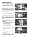
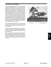
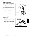
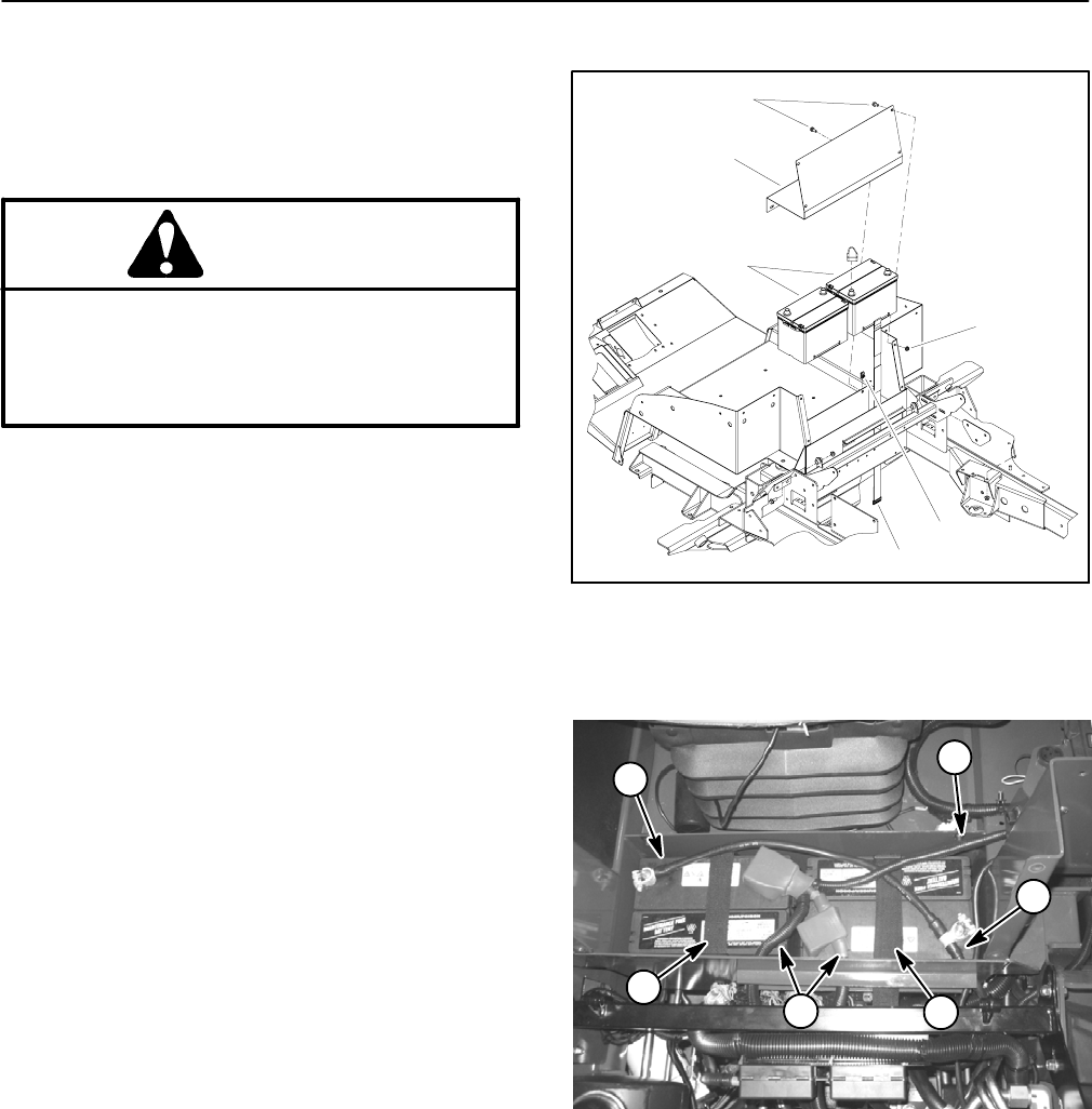
Battery Removaland Installation (Figs. 114 and 115)
1. Remove fasteners that secure battery panel to ma-
chine. Remove panel to access the batteries.
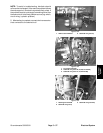
2. Loosen and remove the negative cables from the
batteries. After both negative cables are removed, loos-
en and remove positive cables.
3. Loosen battery straps that secures batteries to ma-
chine.
4. Carefully remove batteries from machine.
5. Install batteries in reverse order making sure to con-
nect and tighten both positive cables to batteries before
connecting the negative cables.
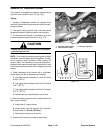
NOTE: Beforeconnectingthenegative(ground) cables
to the battery, connect a digital multimeter ( set to DC
Amps) between the negative battery post and the nega-
tive (ground) cable connector. The reading should be
less than 0.1 amp. If the reading is 0.1 amp or more, the
machine’s electrical system should be tested for short
circuits or faulty components and repaired.
6. Secure batteries with battery straps.
7. Position battery panel in place and secure with re-
moved fasteners.
1. Battery strap (2 used)
2. U--nut (2 used)
3. Flange nut (4 used)
4. Flange screw (6 used)
5. Battery panel
6. Battery (2 used)
Figure 114
2
4
1
3
5
6
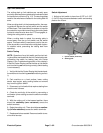
1. Negative (--) cable
2. Positive (+) cable
3. Battery strap
Figure 115
1
2
1
2
3
3