


Groundsmaster 5900/5910Hydraulic System Page 4 -- 94
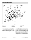
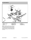
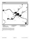
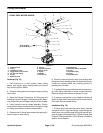
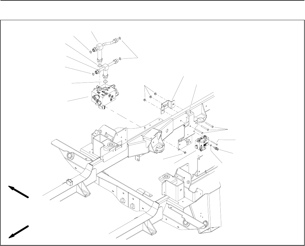
Traction Flush Manifold
1. 4WD control manifold
2. O--ring
3. O--ring
4. Hydraulic tee fitting
5. Hydraulic tee fitting
6. Flange nut
7. Bulkhead mount plate
8. Flange nut (2 used)
9. Cap screw
10. Cap screw (2 used)
11. Hydraulic oil temp sender
12. O--ring
13. Flush manifold assembly
14. Flange screw (4 used)
Figure 67
6
10
8
2
3
1
11
9
7
12
4
5
2
3
3
FRONT
RIGHT
13
14
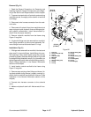
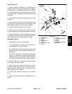
NOTE: The ports on the traction flush manifold are
marked for easy identification ofcomponents. Example:
CV is the c heck valve port and TS is the temperature
sender port (see Hydraulic Schematic in Chapter 10 --
Foldout Drawings to identifythe function of thehydraulic
lines and cartridge valves at each port).
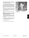
NOTE: The traction flush manifold includes a zero leak
NWD plug. This plug has a tapered sealing surface on
the plug head that isdesigned to resist vibrationinduced
plug loosening. The zero leak plug also has an O--ring
as a secondary seal. If zero leak plug removal is neces-
sary, lightly rap the plug head using a punch and ham-
mer before using an allen wrench to remove the plug:
the impact will allow plug removal with less chance of
damage to the socket head of the plug. When installing
plug, refer to Figure 68 for plug installation torque.
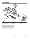
Removal (Fig. 67)
1. Read the General Precautions for Removing and
Installing Hydraulic System Components at the begin-
ning of the Service and Repairs section of this chapter.
2. To preventcontamination ofhydraulic system during
manifold removal, thoroughly clean exterior of manifold
and fittings.
3. Disconnect hydraulic lines from flush manifold and
putcapsorplugs on open hydrauliclinesandfittings.La-
bel disconnected hydraulic lines for proper assembly.