


Groundsmaster 5900/5910 Hydraulic SystemPage 4 -- 95
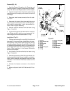
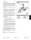
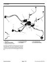
4. Support flush manifold to prevent it from falling. Re-
move two (2) cap screws and flange nuts that secure
manifold to frame (Fig. 67). Remove flush manifold from
the machine.
5. Ifhydraulicfittingsaretoberemovedfromflushman-
ifold, mark fitting orientation to allow correct assembly.
Remove fittings from manifold and discard O--rings.
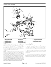
Installation (Fig. 67)
1. If fittings were removed from manifold:
A. Lubricate new o--rings with clean hydraulic oil.
Install lubricated o--rings on fittings.
B. Install fittings into manifoldopenings using marks
made during the removal process to properly orien-
tate fittings.
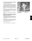
C. Refer to Figure 68 for straight fitting installation
torque. For information on tightening procedures for
adjustable fittings, see Hydraulic Fitting Installation
in the General Information section of this chapter.
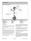
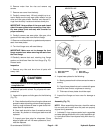
2. Refer to Figure 68 for check valve, shuttle valve and
plug installation torque.
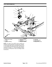
3. Position flush manifold to the frame and secure with
two (2) cap screws and flange nuts.
4. Remove caps and plugs from fittings and hoses.
Properly connect hydraulic lines to manifold (see Hy-
draulic Hose and Tube Installation in the General Infor-
mation section of this chapter).
5. Make sure hydraulic tankis full. Add correct oilifnec-
essary.
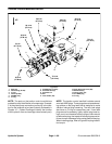
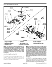
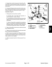
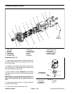
1. O--ring
2. Straight fitting (P2)
3. O--ring
4. #6 NWD plug/O--ring
5. Shuttle valve (HS)
6. Flush manifold
7. Tee fitting (CD)
8. Check valve (CV)
9. O--ring
10. O--ring
11. 90
o
fitting (P1)
Figure 68
6
8
2
3
1
7
4
5
3
1
9
10
11
25 ft--lb
(33 N--m)
35 ft--lb
(47 N--m)
25 ft--lb
(33 N--m)
50 ft--lb
(67 N--m)
UP
Hydraulic
System