


Groundsmaster 5900/5910 Hydraulic SystemPage 4 -- 79
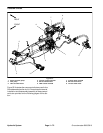
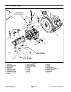
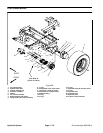
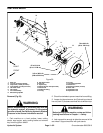
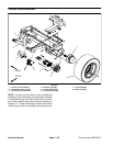
Removal (Fig. 56)
1. Park machine on a level surface, lower cutting
decks, stop engine, apply parking brake and remove
key from the ignition switch.
2. Read the General Precautions for Removing and
Installing Hydraulic System Components at the begin-
ning of the Service and Repairs section of this chapter.
3. To preventcontamination ofhydraulic system during
motor removal, thoroughly clean exterior of motor, hy-
draulic tubes and fittings.
4. To allow easier access to hydraulic tube fittings at
wheelmotor,removepin thatsecures lift cylinder to front
deck lift arm and lower front of lift cylinder (see Front
Deck Lift Cylinder Removal in this section).
5. Disconnect hydraulic tubes from wheel motor. Also,
loosen fittings that are at other end of tubes to allow
tubes to be shifted for wheel motor removal.
6. Put caps or plugs on disconnected hydraulic lines
and fittings to prevent contamination.
IMPORTANT: Before loosening fasteners, support
wheel motor to prevent motorfrom falling during re-
moval.
7. Removetwo(2) cap screws andflatwashers that se-
cure front wheel motor to brake and planetary assem-
blies.
8. Slide front wheel motor from brake assembly and re-
move from machine.
9. Remove and discard O--ring from between wheel
motor and brake assembly.
10.If necessary, remove fittings from wheel motor and
discard fitting O--rings.
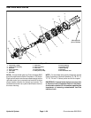
Installation (Fig. 56)
1. If fittings were removed from wheel motor, lubricate
and place new O--rings onto fittings. Install fittings into
motor ports and tighten fittings (see Hydraulic Fitting
Installation in the General Information section of this
chapter).
2. Lightly oil new O--ring (item 9) and place on wheel
motor flange.
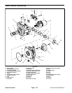
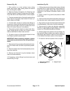
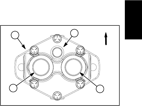
3. Positionwheel motor to brakeassemblymakingsure
that case drain port is above supply line ports (Fig. 57).
4. Align splines on motor shaft and splined brake shaft
in brake assembly. Slide motor into brake assembly.
5. Secure motor to brake and planetary assemblies
with two (2) cap screws and flat washers. Torque cap
screws from 75 to 85 ft--lb (102 to 115 N--m).
6. Remove plugs from hydraulic lines and fittings. At-
tach hydraulic tubes to wheel motor and then tighten all
tube fittings (see Hydraulic Hose and Tube Installation
in the General Information section of this chapter).
7. Fill reservoir with new hydraulic fluid as required.
1. Wheel motor backplate
2. Case drain port
3. Supply line port
Figure 57
UP
3
2
3
1
Hydraulic
System