


Groundsmaster 5900/5910 Hydraulic SystemPage 4 -- 83
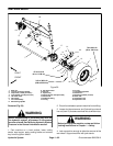
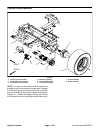
5. Removerear wheel assembly fromthemachine(see
RearWheelRemovalinthe Service andRepairssection
of Chapter 6 -- Chassis).
IMPORTANT: DO NOT hit wheel hub, wheel hub
pullerorwheelmotor with a hammer during removal
or installation. Hammering may cause damage to
the wheel motor.
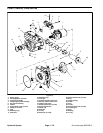
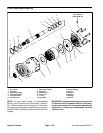
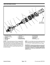
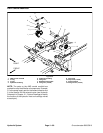
6. Make sure that hex nut (item 10) that secures wheel
hub to wheel motor is loosened at least two (2) turns.
Use hub puller (see Special Tools) to loosen wheel hub
from wheel motor.
7. Removeloosened hex nut and wheel hub frommotor
shaft. Locate and retrieve square key from wheel motor
shaft.
8. Thoroughlycleanhydraulic hose ends and fittings on
rear wheel motor to prevent hydraulic system contami-
nation.
9. Label all hydraulic hoses for assembly purposes.
Remove hydraulic hoses from fittings on wheel motor.
Allow hoses to drain into a suitable container.
10.Remove hydraulic fittings from wheel motor. Re-
move and discard O--rings from fittings.
11.Put cleanplugs in disconnectedhydraulic hoses and
wheel motor ports to prevent system contamination.
12.Support the wheel motor to prevent it from falling dur-
ing removal.
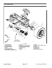
13.Remove four (4) cap screws and lock washers that
secure wheel motor to the steering spindle.
14.Remove wheel motor from frame.
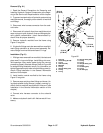
Installation (Fig. 59)
IMPORTANT: Because of internal differences in
rear wheel motors, DO NOT interchange rear wheel
motors on machine (i.e. do not put right side motor
on left side of machine). The left side wheel motor
has a yellow identification mark on the motor hous-
ing. If necessary,use parts catalog and part number
on wheel motor to identify RH and LH motors.
1. Position rear wheel motor to steering spindle. Make
sure that ports in wheel motor are facing toward the r ear
of the machine.
2. Secure wheel motor to spindle with four (4) c ap
screws and lock washers. Torque screws from 67 to 83
ft--lb (91 to 112 N--m).
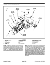
3. Remove plugs from disconnected hydraulic hoses
and wheel motor ports.
4. Lubricate and install new O--rings to hydraulic fit-
tings. Install fittings into wheel motor ports (see Hydrau-
lic Fitting Installation in the General Information section
of this chapter).
5. Remove caps or plugs placed during removal to pre-
vent contamination.
6. Using labels placed during the removal process,
properly connect hydraulic hoses to wheel motor fittings
(see Hydraulic Hose and Tube Installation in the Gener-
al Information section of this chapter).
7. Make sure that tapers of wheel motor shaft and
wheel hub are thoroughly clean.
8. Position square key to keyslot in wheel motor shaft.
IMPORTANT: Do not reuse hex nut that secures
wheel hub to wheelmotor after it hasbeen removed.
9. Place wheel hub on motor shaft and secure withnew
hex nut (item 10).
10.Install wheel assembly to the machine and secure
with six (6) lug nuts.
11.Lower the machine to the ground.
Failure to properly tighten nut that secures
wheel hub or wheel lug nuts could result in fail-
ure or loss of wheel and may result in personal
injury.
WARNING
12.Torque hex nut (item 10) from 315 to 385 ft--lb (428
to 522 N --m).
13.Torque wheel lug nuts from 70 to 90 ft--lb (95 to 122
N--m).
14.Make surehydraulic tank is full.Addcorrect oil if nec-
essary.
15.After assembly is completed, verify that hydraulic
hoses and fittings do not contact anything through full
range of axle motion. Also, check for any hydraulic
leaks.
Hydraulic
System