


Groundsmaster 5900/5910 Hydraulic SystemPage 4 -- 127
NOTE: Theports on the liftcontrol manifold aremarked
for easy identification andassemblyof components. Ex-
ample: P1 is the supply port from the gear pump and FD
is the flow divider cartridge location (see Hydraulic
Schematic in Chapter 10 -- Foldout Drawings to identify
the function of the hydraulic lines and cartridge valves
at each port).
NOTE: The lift control manifold includes several zero
leak NWD plugs. These plugs have a tapered sealing
surface on the plug head that is designed to resist vibra-
tion induced plug loosening. The zero leak plugs also
have an O--ring as a secondary seal. If zero leakplug re-
moval is necessary, lightly rap the plug head using a
punch and hammer before using an allen w rench to re-
move the plug: the impact w ill allow plug removal with
less chance of damage to the socket head of the plug.
When installing plugs, refer to manifold illustration for
plug installation torque.
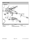
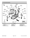
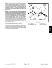
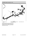
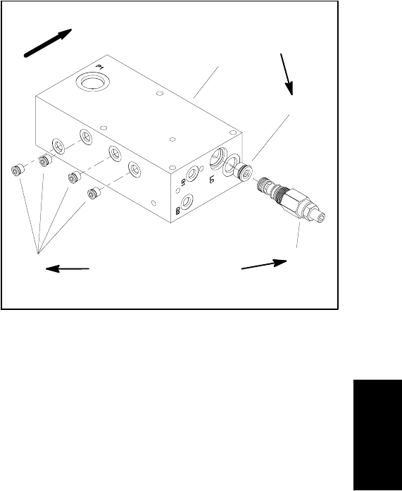
Valve Cartridge Service (Figs. 92 and 93)
For cartridge valve service procedures, see Hydraulic
Traction Control Manifold Service in this section. Refer
to Figures 92 and 93 for lift control manifold cartridge
valve and plug installation torque.
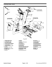
1. Lift manifold
2. NWD #8 plug/O--ring
3. Logic valve (LC)
4. SAE #4 plug/O--ring
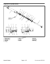
Figure 93
2
1
3
4
50 ft--lb
(67 N--m)
25 ft--lb
(33 N--m)
20 ft--lb
(27 N--m)
UP
Hydraulic
System