


Groundsmaster 5900/5910 Hydraulic SystemPage 4 -- 75
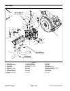
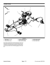
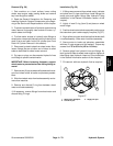
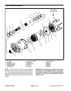
Removal (Fig. 54)
1. Park machine on a level surface, lower cutting
decks, stop engine, apply parking brake and remove
key from the ignition switch.
2. Remove hood to gain access to hydraulic pumps
(see Hood Removal in the Service and Repairs section
of Chapter 7 -- Chassis).
3. Drain the hydraulic reservoir.
4. To preventcontamination ofhydraulic system during
pump removal, thoroughly clean exterior of pump as-
sembly including hydraulic hoses.
5. For assembly purposes, label wire harness leads for
traction pump solenoids. Disconnect wire harness con-
nectors from two (2) solenoids on pump.
6. Read the General Precautions for Removing and
Installing Hydraulic System Components at the begin-
ning of the Service and Repairs section of this chapter.
7. Label all hydraulic hose connections for assembly
purposes.
8. Put a drain pan below the pump assembly. Remove
allhydraulichosesconnectedtopiston and gearpumps.
Put plugs or caps on disconnected hydraulic hoses and
fittings to prevent contamination of the system.
9. Remove gear pump from machine (see Gear Pump
Removal in this section).
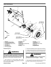
CAUTION
Make sure piston pump is properly supported
before removing the pump mounting screws.
Piston pump assembly weighs approximately 86
pounds (39 kg).
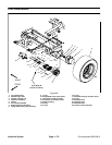
10.Attach hoist to piston pump to support pump and also
to allow safe removal of pump from machine.
11.Remove two (2) c ap screws and washers that retain
pump assembly to flywheelcoupling housingon engine.
12.Carefully slide pump assembly from housing on en-
gine and raise pump out of the machine.
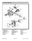
13.If hydraulic fittings are to be removed from piston
pump, mark fitting orientation to allow correct assembly.
Remove fittings from pump and discard O--rings.
Installation (Fig. 54)
1. If fittings were removed from piston pump, lubricate
and place new O--rings onto fittings. Install fittings into
pump openings using marks made during the removal
process to properly orientate fittings. Tighten fittings
(see Hydraulic Fitting Installation in the General Infor-
mation section of this chapter).
2. Attachhoisttopistonpumptosupportpumpandalso
to allow safe installation of pump into machine.
3. Carefully lower piston pump into the machine and
position it to the flywheel coupling housing on engine.
Support pump to make sure that side loads are not ap-
plied to flywheel coupling and that pump pilot is aligned
with coupling housing on engine. Support pump to pre-
vent it from shifting or falling while installing two (2) cap
screws and washers securing piston pump to engine
housing. Torque screws from 135 to 165 ft--lb (184 to
223 N--m).
4. Install gear pump to piston pump (see Gear Pump
Installation in this section).
5. Using labels placed during removal, correctly con-
nect two (2) wire harness connectors to solenoids on
traction pump.
6. Remove plugs or caps from disconnected hydraulic
hoses. Install hoses to correct location on gear and pis-
ton pumps (see Hydraulic Hose and Tube Installation in
the General Information section of this chapter).
7. Remove and replace hydraulic filters.
8. Fill hydraulic reservoir with correct oil.
9. Properly fill hydraulic system (see Charge Hydraulic
System in this section).
10.Stop engine and check for hydraulic oil leaks. Check
hydraulic reservoir oil level.
11.Install hood (see Hood Installation in theService and
Repairs section of Chapter 7 -- Chassis).
Hydraulic
System