


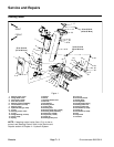
Groundsmaster 5900/5910 Page 6 -- 19 Axles, Planetaries and Brakes
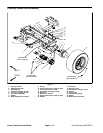
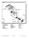
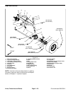
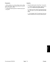
Removal (Fig. 13)
1. Park machine on a level surface, lower cutting
decks, stop engine, engage parking brake and remove
key from the ignition switch.
2. Chock front wheels to preventmachinefrom shifting.
3. Thoroughlycleanhydraulic hose ends and fittings on
steering cylinders and rear wheel motors to prevent hy-
draulic system contamination.
NOTE: To ease assembly, label hydraulic hoses to
show their correct position on the steering cylinders and
rear wheel motors.
4. Disconnect the hydraulic hoses from the steering
cylinders and rear wheel motors. Put caps or plugs on
all fittings and hoses to prevent contamination.
5. Remove the lock nut (item 12) and thrust washer
(item 19) that secures the axle pivot shaft (item 13) to the
frame.
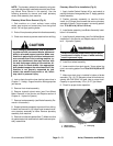
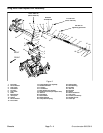
CAUTION
When changing attachments, tires or perform-
ing other service,use correct blocks, hoistsand
jacks to raise and support machine. Make sure
machine is parked on a solid level surface such
as a concrete floor. Prior to raising machine, re-
move any attachments that may interfere with
the safe and proper raising of the machine. Al-
ways chock or block wheels. Use appropriate
jack stands to support the raised machine.If the
machine is not properly supported by jack
stands, the machine may move or fall, which
may result in personal injury.
6. Jack up the machine (just ahead of the rear wheels)
until clearance exists to allow rear axle removal. Sup-
port the machine with appropriate jack stands prevent it
from falling.
7. Support rear axle to prevent it from falling.
8. Pull the axle pivot shaft from frame and rear axle.
This will releasethe rear axle andtwo (2) thrustwashers
(item 19) from the frame. Carefully lower the entire axle
assembly and remove it from under the machine.
NOTE: If service to the rear wheel motors or steering
cylinders is required, refer to the Service and Repairs
section of Chapter 4 -- Hydraulic System.
Installation (Fig. 13)
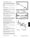
1. Thoroughly clean the rear axle pivot s haft. Inspect
the shaft for wear or damage and replace if necessary.
2. Position the rear axle assembly to the frame. Install
thrust washer (item 19) between each side of axle and
frame. Raise axle assembly to frame and slide pivot
shaft through frame, thrust washers and axle. Make
sure that roll pin on pivot shaft is positioned in frame re-
liefs.
3. Install thrust washer (item 19) and lock nut (item 12)
onto pivot shaft. Tighten lock nut to eliminate any axial
movementofrearaxle. Make sure thataxlecan still pivot
freely after lock nut is tightened.
4. Lower the machine to the ground.
5. Correctly install the hydraulic hoses to the steering
cylinders and rear wheel motors.
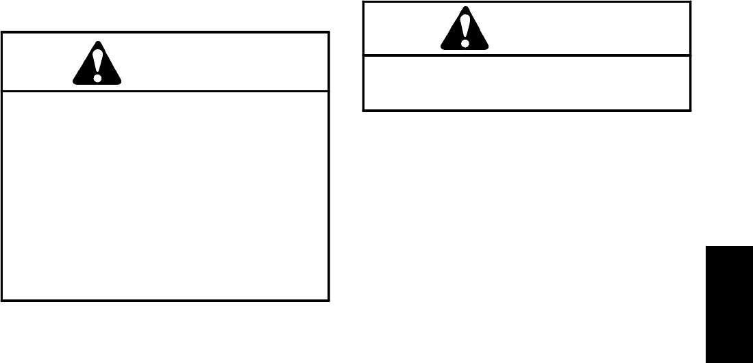
Failure to maintain proper wheel lug nut torque
could result in failure or loss of wheel and may
result in personal injury.
WARNING
6. Make sure that wheel lug nuts are properly torqued
from 70 to 90 ft--lb (95 to 122 N--m).
7. Check oil level in hydraulic reservoir.
8. Lubricate the rear axle pivot bushings through the
grease fitting on the rear axle.
9. Operate machine and check hydraulic connections
at steering cylinders and wheel motors for leaks.
10.After assembly and adjustments have been com-
pleted, make sure that no contact is made between any
machine components as the rear wheels are moved
from steering lock to lock. Readjust if necessary.
Axles, Planetaries
and Brakes