


Groundsmaster 5910 Operator CabPage 9 -- 13
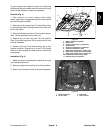
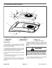
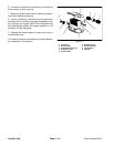
Removal (Fig. 9)
1. Park machine on a level surface, lower cutting
decks, stop engine, engage parking brake and remove
key from the ignition switch.
2. Remove fasteners that secure roof in place. Raise
and supportroofto allow access to condenser assembly
(see Roof Assembly Removal in this section).
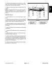
3. Disconnect wire harness connectors from fan motor
and binary switch on drier--receiver.
4. Read the General Precautions for Removing and
Installing Air Conditioning System Components at the
beginning of the Service and Repairs section of this
chapter.
CAUTION
The air conditioning system is under high pres-
sure. Do not loosen any system fitting or compo-
nent until after the system has been completely
discharged by a certified A/C service technician.
5. Have refrigerant evacuated from air conditioning
system by a certified A/C service technician.
6. Label and remove hoses from heater core, evapora-
tor and drier--receiver. Immediately cap hoses and fit-
tings to prevent moisture and contaminants from
entering the system.
7. Loosen hose clamp that secures air duct hose to
heater and evaporator assembly covers. Slide hose
from covers.
8. Removescrews that securetop cover tobottom cov-
er. Remove top cover to access heater and evaporator
assembly.
9. Disassemble heater andevaporator assembly using
Fig. 12 as a guide.
NOTE: Thereplacement of the drier--receiver is recom-
mended whenever the air conditioning system is
opened.
Installation (Fig. 9)
1. Assemble heater and evaporator assembly using
Fig. 12 as a guide. Make sure that expansion valve is
covered with insulating tape to prevent condensation is-
sues.
2. Position heater and evaporator assembly into bot-
tomcoverinheadliner.Secure top cover to bottomcover
with removed screws.
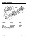
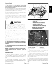
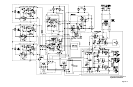
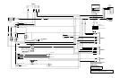
1. Heater evaporator assembly
2. Heater valve
3. A/C hose: evaporator to compressor
4. Air duct hose
5. A/C hose: compressor to condenser
6. A/C hose: condenser to drier
7. Heater hose: thermostat to heater valve
8. Heater hose: heater core to water pump
9. Heater hose: heater valve to heater core
10. Condensation drain hose (2 used)
11. A/C hose: drier to evaporator
Figure 10
2
1
3
4
7
8
6
5
9
10
11
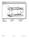
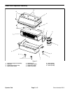
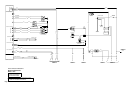
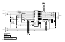
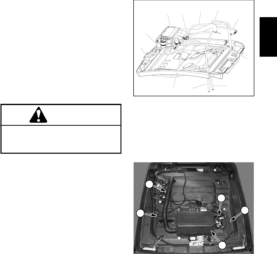
1. Heater evaporator
2. Air duct hose
3. Drain hose
4. Drier--receiver
Figure 11
1
2
4
3
3
3. Slide air duct hose onto heater and evaporator as-
sembly covers and secure with hose clamp.
4. Remove caps that were placed on hoses and fittings
during the removal process. Using labels placed during
removal, properly secure hoses to heater core, evapo-
rator and drier--receiver.
5. Make sure that condensation hoses are secured to
bottom housing of heater and evaporator assembly and
are routed to cab frame for proper draining of conden-
sate.
Operator
Cab