


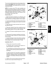
Groundsmaster 5900/5910Hydraulic System Page 4 -- 98
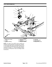
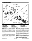
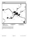
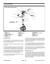
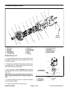
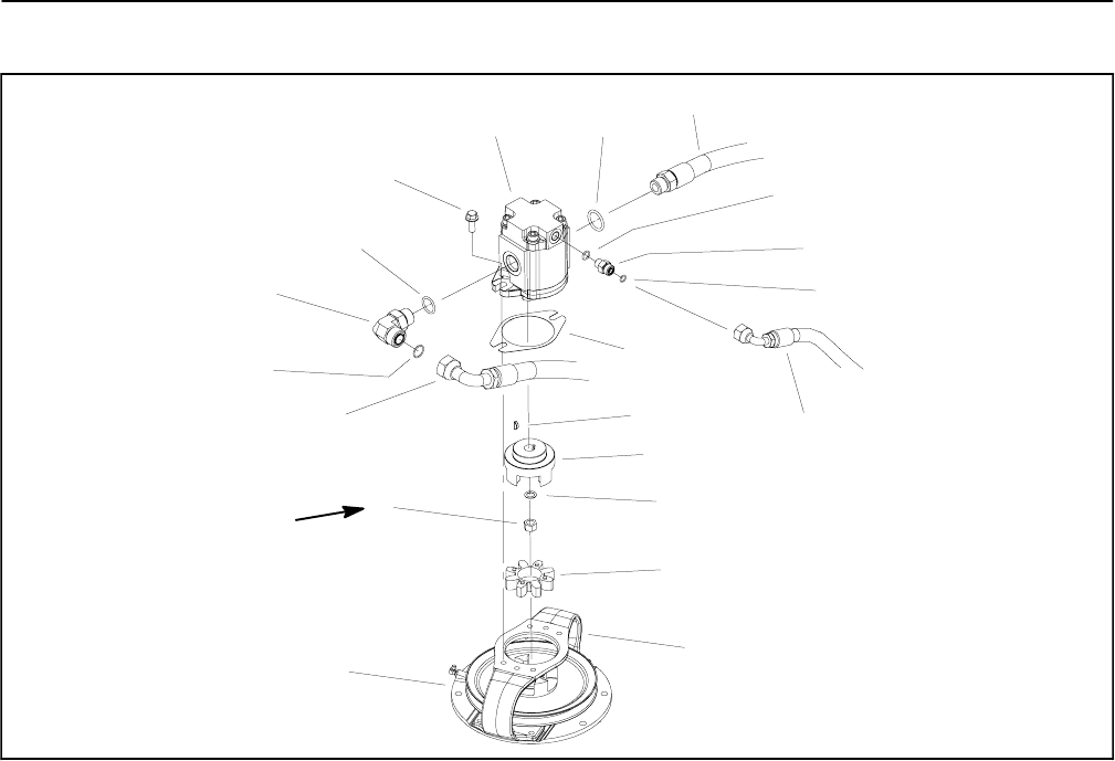
Cutting Deck Motor
1. Hydraulic hose
2. O--ring
3. Cutting deck motor
4. Flange head screw (2 used)
5. 90
o
hydraulic fitting
6. O--ring
7. Hydraulic hose
8. Hex nut
9. Spindle assembly
10. Motor mount
11. Spider
12. Washer
13. Spider hub
14. Woodruff key
15. Mounting shim (if equipped)
16. O--ring
17. Hydraulic fitting
18. O--ring
19. Hydraulic hose
Figure 70
7
4
10
12
8
9
6
5
11
1
2
3
2
13
16
14
17
15
18
19
27 to 33 ft--lb
(37to44N--m)
FRONT DECK MOTOR SHOWN
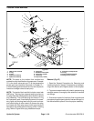
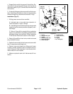
Removal (Fig. 70)
1. Park machine on a level surface, lower cutting
decks, stop engine, apply parking brake and remove
key from the ignition switch.
2. Remove cutting deck cover to gain access to cutting
deck motor.
3. Read the General Precautions for Removing and
Installing Hydraulic System Components at the begin-
ning of the Service and Repairs section of this chapter.
4. Label hydraulic lines for proper assembly. Discon-
nect hydraulic hoses from deckmotor. Put caps or plugs
on fittings and hoses to prevent contamination.
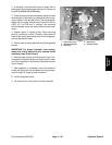
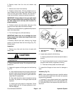
5. Remove two (2) flange head screws that secure hy-
draulic motor to motor mount.
6. Carefully remove hydraulic motor from cutting deck
taking care not to damage spider hub attached to motor.
Locate and remove spider and mounting shim(s) (if
present) from the deck.
7. If hydraulic fittings are to be removed from deck mo-
tor, mark fitting orientation to allow correct assembly.
Remove fittings from motor and discard O --rings.
8. If required, remove hex nut and washer that secure
spider to motor shaft. Use suitable puller to remove hub
from shaft. Remove woodruff key.
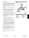
Installation (Fig. 70)
1. If fittings were removed from deck motor, lubricate
and place new O--rings onto fittings. Install fittings into
motor ports using marks made during the removal pro-
cess to properly orientate fittings. Tighten fittings (see
Hydraulic Fitting Installation in the General Information
section of this chapter).