


Groundsmaster 5900/5910Page 7 -- 10Chassis
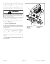
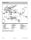
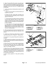
3. Align lift cylinder with lift arm. Slide lift cylinder pin
through lift arm and cylinder end. Secure pin with flange
head screw and flange nut.
4. Install front wheel assembly (see Wheel Installation
in the Service and Repairs section of Chapter 6 -- Axles,
Planetaries and Brakes). Lower machine to the ground.
Failure to maintain proper wheel lug nut torque
could result in failure or loss of wheel and may
result in personal injury.
WARNING
5. Torque wheel lug nuts evenly in a crossing pattern
from 70 to 90 ft--lb (95 to 122 N--m).
6. Install cutting deck (see C utting Deck Installation in
Chapter 8 -- Cutting Deck).
7. Lubricate lift arm grease fittings.
8. Afterassemblyis completed, raise and lower the cut-
ting deck to verify that hydraulichoses andfittingsdonot
contact anything.
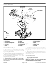
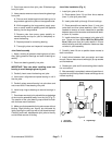
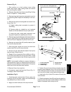
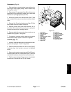
9. When lift arms are fully raised, check that gap be-
tween lift arms and bumper pads on bottom of operator
platform is approximately 0.100” (2.5 mm) (Fig. 8). If
necessary, add or remove shim pads so that gap is cor-
rect.
10.Verify correct operation of front deck proximity
switch.
11.Check height--of--cut and deckpitch adjustment. Ad-
just if necessary.
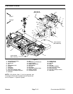
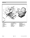
1. Operator platform
2. Shim pad
3. Bumper pad
4. Flange head screw
5. Flange nut
Figure 8
3
1
4
5
2