


Groundsmaster 5900/5910 Hydraulic SystemPage 4 -- 53
Procedure for Lift/Lower Circuit Relief Pressure
Test
NOTE: Before attempting to check or adjust lift pres-
sure, make s ure that counterbalance pressure is cor-
rectly adjusted.
1. Make sure hydraulic oil is at normal operating tem-
perature by operating the machine for approximately 10
minutes. Make sure the hydraulic tank is full.
2. Park machine on a level surface with the cutting
decks lowered and off. Make sure engine is off and the
parking brake is applied.
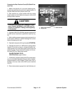
CAUTION
Prevent personal injury and/or damage to equip-
ment. Read all WARNINGS, CAUTIONS and Pre-
cautions for Hydraulic Testing at the beginning
of this section.
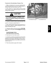
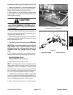
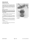
3. Connecta 5000 PSI (350 Bar) pressure gauge to test
port G3 on lift control manifold (Fig. 37). Route gauge
hose to allow operator to view the gauge.
4. After installing pressure gauge, start engine and run
at idle speed. Check for hydraulic leakage and correct
before proceeding with test.
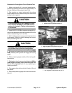
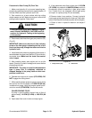
5. Sit on the seat and operate the engine at full speed
(2750 RPM).
6. While sitting on the seat, press and hold one of the
deck lift switches to fully raise a cutting deck. Momen-
tarily holdtheswitchwiththedeckfullyraisedwhilelook-
ing at the gauge.
GAUGE READING TO BE:
1350 PSI (93 bar) (approximate).
7. Stop engine and record test results.
NOTE: Do not remove relief valve from the hydraulic
manifold for adjustment.
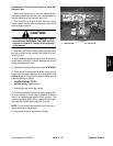
8. If relief pressure is too high, remove cap on relief
valve (RV) in lift control manifold (Fig. 37). Adjust valve
by rotating adjustment socket counterclockwise to de-
crease relief pressure (see Adjustable Pressure Valve
in the Adjustments section of this chapter). A 1/8 turn on
the socket willmake a measurable change in relief pres-
sure. Recheck relief pressure and readjust as needed.
Install and tighten cap on relief valve after adjustment.
9. If relief pressure is too low, check for restriction in
gear pump intake line or reservoir strainer. Check the lift
cylinder for internal leakage. Ifcylinder is not leaking,re-
move cap onrelief valve (RV) in liftcontrol manifold (Fig.
37) and adjust valve by rotating adjustment socket
clockwise to increase relief pressure (see Adjustable
Pressure Valve in the Adjustments section of this chap-
ter). A 1/8 turn on the socket will make a measurable
change in relief pressure. R echeck relief pressure and
readjustasneeded.Ifpressure is stilltoolow,gearpump
(P3) or lift cylinder(s) should be suspected of wear,dam-
age or inefficiency. Install and tighten cap on relief valve
after adjustment.
10.Disconnect pressure gauge from test port.
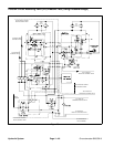
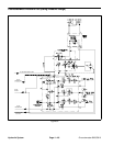
1. Lift circuit test port G3 2. Relief valve RV
Figure 37
1
2
Hydraulic
System