


Groundsmaster 5900/5910Hydraulic System Page 4 -- 102
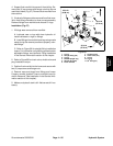
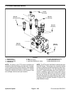
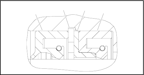
2. Install new seals into front flange (Fig. 76):
A. Press s haft seal into front flange until it reaches
the bottom of the bore.
B. Install flange washer into front flange and then
install retaining ring into the groove of the front
flange.
C. Install new dust seal into front flange.
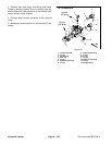
3. Place front flange, seal side down, on a flat surface.
4. Install the pressure seals, flat side outward, into the
grooves in the wear plates. Follow by carefully placing
the backup gaskets, flat side outward, between the
pressure seals and the grooves in the wear plate.
5. Applyalightcoatingofpetroleumjellytotheexposed
side of the front flange.
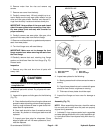
6. Lubricatethe drive gear shaft with clean hydraulic oil.
Insert the drive end of the drive shaft through the wear
platewiththepressuresealsidedownandtheopenside
of the pressure seal pointing to the inlet side of the mo-
tor. Carefully install shaft into front flange.
7. Lubricate the idler gear shaft with clean hydraulic oil.
Install idler gear shaft into the remaining position in the
front wear plate. Apply a light coating of c lean hydraulic
oil to gear faces.
8. Install rear wear plate with pressure seal side up and
open side of the pressure seal pointing to the inlet side
of the motor.
9. Apply a light coating of petroleum jelly to new O--
rings and O--ring grooves in the body. Install new O--
rings to the body.
10.Install locating dowels in body. Align marker line on
the body and front flange.
IMPORTANT: Do not dislodge seals during installa-
tion.
11.Gently slide the body onto the assembly. Firm hand
pressure should be sufficient to engage the dowels.
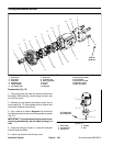
1. Dust seal
2. Retaining ring
3. Flange washer
4. Shaft seal
Figure 76
1
2
3
4
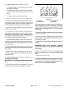
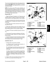
12.Check to make s ure that the surface of the rear wear
plate is slightly below the face of the body. If the wear
plate is not below the body,check assemblyfor ashifted
pressure seal, backup gasket or O--ring. Correct before
proceeding.
13.Apply a light coating of petroleum jelly to the exposed
side of the rear cover.
14.Place rear cover on assembly using marker line for
proper location. Firm hand pressureshould be sufficient
to engage the dowels.
15.Install the four (4) cap screws withwashers and hand
tighten.
IMPORTANT: Avoid using excessive clamping
pressure on the motor housing t o preventdistorting
the housing.
16.Place front flange of the motor into a vise with soft
jaws and alternately torque the cap screws 33 ft--lb (45
N--m).
17.Remove motor from vise.
18.Place a small amount of clean hydraulic oilin the inlet
ofthemotorandrotate the drive shaft away from the inlet
one revolution. If any binding is noted, disassemble the
motor and check for assembly problems.