


Groundsmaster 5900/5910 Hydraulic SystemPage 4 -- 59
Procedure for Gear Pump (P3) Flow Test
1. Make sure hydraulic oil is at normal operating tem-
perature by operating the machine for approximately 10
minutes. Make sure the hydraulic tank is full.
2. Park machine on a level surface with the cutting
decks lowered and off. Make sure engine is off and the
parking brake is applied. Raise hood.
CAUTION
Prevent personal injury and/or damage to equip-
ment. Read all WARNINGS, CAUTIONS and Pre-
cautions for Hydraulic Testing at the beginning
of this section.
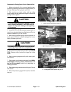
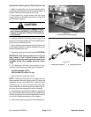
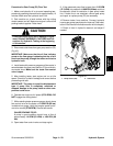
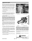
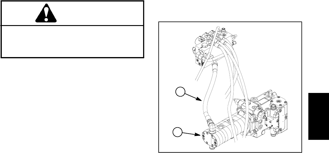
3. Disconnect outlet hose from gear pump section (P3)
(Fig. 43).
IMPORTANT: Make sure that the oil flow indicator
arrow on the flow gauge is showing that the oil will
flow from the pump, through the tester and into the
hydraulic hose.
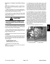
4. Install tester with pressure gauges and flow meter in
series between the gear pump section (P3) and the dis-
connected hose. Make sure the tester flow control
valve is open.
5. After installing tester, start engine and run at idle
speed. Check for hydraulic leakage and correct before
proceeding with test.
IMPORTANT: The pump is a positive displacement
type. If pump flow is completely restricted or
stopped, damage to the pump, tester or other com-
ponents could occur.
6. Operate the engine at full speed (2750 RPM). DO
NOT engage the cutting decks.
7. While watching tester pressure gauges, slowly close
flow control valve on the tester until 1000 PSI (69 bar)
is obtained on gauge. Verify that engine speed contin-
ues to be correct (2750 RPM). Record test results.
GAUGE READING TO BE:
A pump in good condition should have a flow of
approximately 14 GPM (53 LPM) at 1000 PSI (69
bar).
8. Open tester flow control valve and stop engine.
9. If the measured pump flow is lower than 12.5 GPM
(47.3 LPM) or a pressure of 1000 PSI (69 bar) could not
be obtained, check for restriction in gear pump intake
line. If intake line is not restricted, remove gear pump
and repair or replace pump (P3) as necessary.
10.Remove tester from machine. Connect hydraulic
hosetogearpump( see Hydraulic Hose andTubeInstal-
lation in theGeneralInformation section of thischapter).
11.Check oil level in hydraulic reservoir and adjust if
needed.
1. Pump section (P3) 2. Outlet hose
Figure 43
1
2
Hydraulic
System