


Groundsmaster 5900/5910Cutting Decks Page 8 -- 16
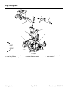
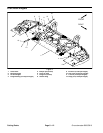
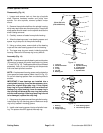
Blade Spindle Service
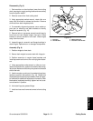
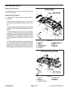
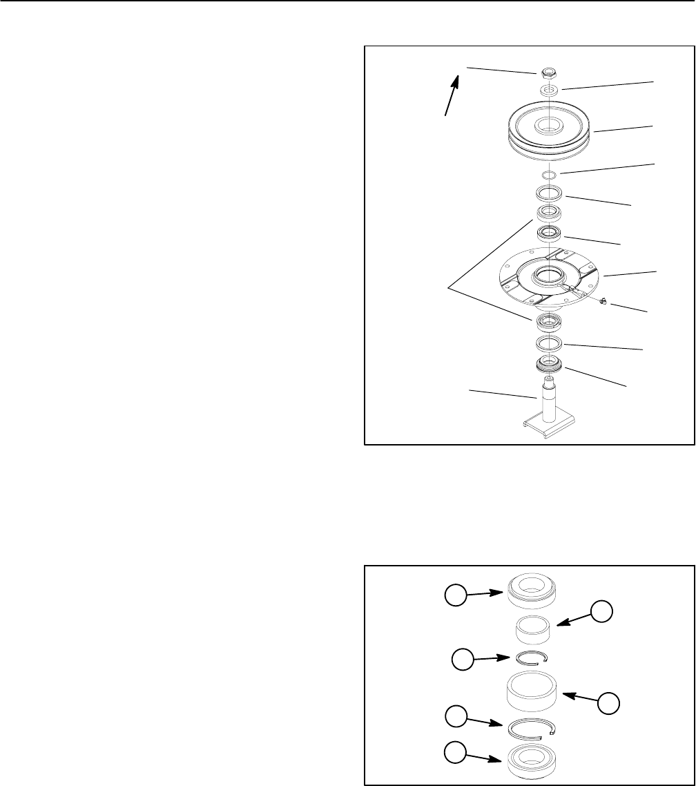
Disassembly (Fig. 14)
1. Loosen and remove lock nut from top of spindle
shaft. Remove hardened washer and pulley from
spindle. For drive spindle, remove hydraulic motor
mount.
2. Remove the spindle shaft from the spindle housing
whichmayrequire the useofanarbor press. Thespindle
shaft spacer should remain on the spindle shaft as the
shaft is being removed.
3. Carefully remove oil seals from spindle housing.
4. Allow the bearing cones, inner bearing spacer and
spacer ring to drop out of the spindle housing.
5. Using an arbor press, remove both of the bearing
cups and the outer bearing spacer from the housing.
6. The large snap ring can remain inside the spindle
housing. Removal of this snap ring is very difficult.
Assembly (Fig. 14)
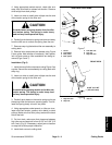
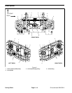
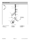
NOTE: Areplacement spindle bearing set contains two
(2) bearings, a spacer ring and a large snap ring (items
1, 2 and 3 in Fig. 15). These parts cannot be purchased
separately. Also, do not mix bearing set components
from one deck spindle to another.
NOTE: A replacement bearing s pacer set includes the
inner spacer and outer spacer (items 4 and 5 in Fig. 15).
Do not mix bearing spacers from one deck spindle to
another.
IMPORTANT: If new bearings are installed into a
used spindle housing,itmay not benecessary to re-
place the original large snap ring. If the original
snap ring is in good condition with no evidence of
damage (e.g. spun bearing), leave the snap ring in
the housing and discard the snap ring that comes
with the new bearings. If the large snapring is found
to be damaged, replace the snap ring.
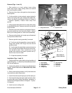
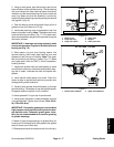
1. Iflargesnapringwas removed from spindle housing,
install snap ring into housing groove. Make sure snap
ring is fully seated in housing groove.
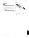
2. Install outer bearing spacer into top of spindle hous-
ing. The spacer should fit against the snap ring.
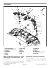
1. Lock nut
2. Hardened washer
3. Pulley
4. O--ring
5. Oil seal
6. Bearing set
7. Spacer set
8. Spindle housing
9. Grease fitting
10. Shaft spacer
11. Spindle shaft
Figure 14
5
3
2
1
10
8
4
6
7
9
11
130 to 150 ft--lb
(176 to 203 N--m)
5
1. Bearing
2. Spacer ring
3. Large snap ring
4. Inner bearing spacer
5. Outer bearing spacer
Figure 15
4
1
1
2
3
5