


Groundsmaster 5900/5910 Page 3 -- 15 Diesel Engine
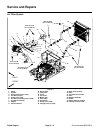
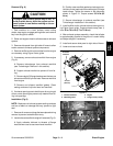
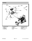
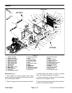
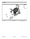
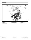
Fuel Tank Removal (Fig. 12)
1. Park machine on a level surface, lower cutting
decks, stop engine, engage parking brake and remove
key from the ignition switch.
2. Chock rear wheels and jack up front of machine.
Support machine on jack stands. R emove front, left
wheel to allow fuel tank removal.
3. Use a fuel transfer pump to remove fuel from the fuel
tank and into a suitable container.
4. Removethree(3)socketheadscrewsthatsecurefit-
ting cover (item 1) to fuel tank. Remove fitting cover.
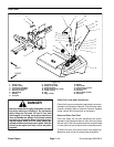
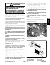
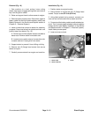
5. Disconnect power (blue/red) and ground (black)
wires from the fuel sender on the fuel tank (Fig. 13).
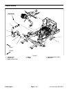
6. Label fuel hoses to assure properassembly.Discon-
nect fuel hoses from the fuel supply standpipe (item 3),
the return standpipe (item 4) and the vent elbow fitting
(item 6) in top of tank (Fig. 13).
7. Route fuel lines from under clamps (item 13) that
route fuel lines from standpipes. If necessary, remove
plugs and clamps from top of tank.
8. Remove two (2) flange head screws and lock nuts
that secure tank hold down (item 11) to frame. Remove
tank hold down.
9. Slide fuel tank from left side of machine to remove
tank.
10.If necessary, remove standpipes, elbow bushings
and fuel sender from fuel tank.
Fuel Tank Installation (Fig. 12)
1. If removed, install standpipes, elbow bushings and
fuel sender into fuel tank.
2. Install fuel tank from left side of machine.
3. Position tank hold down (item 11) to fuel tank and
machine frame. Secure hold down with two (2) flange
head screws and lock nuts.
4. Route fuel supply and return hoses under clamps in
top of tank.
5. Using labels placed during tank removal, correctly
connect fuel hoses to the fuel supply standpipe, the re-
turn standpipe and the vent elbow fitting. Secure hoses
with hose clamps.
6. Connect electrical wiring to the fuel sender.
A. Connect blue/red wire to the center terminal and
black wire to any of the screws that secure the fuel
sender to the fuel tank.
B. Apply skin--over grease (Toro Part No. 505--165)
to the wire terminal connections.
7. Position fitting cover to fuel tank and secure with
three (3) socket head screws.
Failure to maintain proper torque could result in
failure or lossof wheeland may result inperson-
al injury.
WARNING
8. Install front, left wheel assembly.
9. Lower machine to ground. Torque wheel lug nuts in
a crossing pattern from 70 to 90 ft--lb (95 to 122 N--m) .
10.Fill fuel tank.
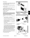
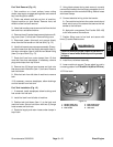
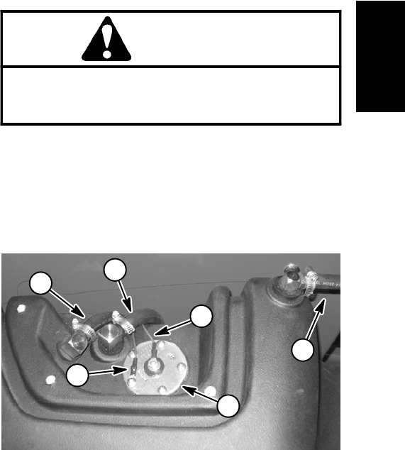
Figure 13
1. Sender power wire
2. Sender ground wire
3. Fuel sender
4. Fuel supply hose
5. Return fuel hose
6. Vent hose
5
6
4
1
2
3
Diesel
Engine