


Chapter 1 29
Signal Generator Overview
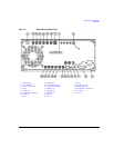
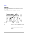
Rear Panel
27. TRIGGER OUT
This female BNC connector, in step/list sweep mode, outputs a TTL signal that is high at the start of
a dwell sequence or when waiting for a point trigger in manual sweep mode. The signal is low when
the dwell is over or when a point trigger is received. In ramp sweep mode, the output provides 1601
equally spaced 1 μs pulses (nominal) across a ramp sweep. When using LF Out, the output provides
a 2 μs pulse at the start of an LF sweep. The nominal impedance for this connector is less than
10 ohms.
28. TRIGGER IN
This female BNC connector accepts a 3.3V CMOS signal, which is used for point-to-point triggering in
manual sweep mode, or in a low frequency (LF output) or analog (AM, FM, and ΦM) external sweep
trigger setup. Triggering can occur on either the positive or negative edge of the signal start. The
damage level is ≤ −4V or ≥+10 V. The nominal input impedance for this connector is approximately
4.2 kohms.
29. SOURCE SETTLED
This female BNC connector provides a 3-volt CMOS output trigger, indicating when the signal
generator has settled to a new frequency or power level. A high indicates that the source has not
settled. A low indicates that the source has settled. The nominal output impedance for this connector
is less than 10 ohms.
30. SOURCE MODULE INTERFACE
This interface is used to connect to compatible Agilent Technologies 83550 Series mm-wave source
modules.
31. RF OUT
This connector outputs RF and microwave signals. The nominal output impedance is 50 ohms. The
reverse power damage levels are 0 Vdc, 0.5 watts nominal. On signal generators without Option 1EM,
this connector is located on the front panel. The connector type varies according to frequency option.
32. EXT 1
This female BNC input connector (functional only with Options UNT, UNU, or UNW) accepts a ±1V
p
signal for AM, FM, and ΦM. For these modulations, ±1V
p
produces the indicated deviation or depth.
When ac-coupled inputs are selected for AM, FM, or ΦM and the peak input voltage differs from 1 V
p
by more than 3 percent, the HI/LO display annunciators light. The input impedance is selectable as
either 50 or 600 ohms; the damage levels are 5 V
rms
and 10 V
p
. On signal generators without Option
1EM, this connector is located on the front panel.