


128 Chapter 4
Optimizing Performance
Creating and Applying User Flatness Correction
4. Ensure that the file FLATCAL1 is highlighted.
5. Press
Load From Selected File > Confirm Load From File.
This populates the user flatness correction array with the data contained in the file FLATCAL1.
The user flatness correction array title displays User Flatness: FLATCAL1.
6. Press
Return > Flatness Off On to On.
This applies the user flatness correction data contained in FLATCAL1.
Returning the Signal Generator to GPIB Listener Mode
During the user flatness correction process, the power meter is slaved to the signal generator via
GPIB, and no other controllers are allowed on the GPIB interface. The signal generator operates in
GPIB talker mode, as a device controller for the power meter. In this operating mode, it cannot
receive SCPI commands via GPIB.
If the signal generator is to be interfaced to a remote controller after performing the user flatness
correction, its GPIB controller mode must be changed from GPIB talker to GPIB listener.
If an RF carrier has been previously configured, you must save the present instrument state before
returning the signal generator to GPIB listener mode.
1.
Save your instrument state to the instrument state register.
For instructions, see “Saving an Instrument State” on page 57.
2. Press
Amplitude > More (1 of 2) > User Flatness > GPIB Listener Mode.
This presets the signal generator and returns it to GPIB listener mode. The signal generator can
now receive remote commands executed by a remote controller connected to the GPIB interface.
3. Recall your instrument state from the instrument state register.
For instructions, see “Saving an Instrument State” on page 57.
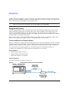
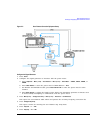
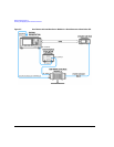
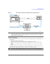
Creating a User Flatness Correction Array with a mm-Wave Source Module
In this example, a user flatness correction array is created to provide flatness-corrected power at the
output of an Agilent 83554A millimeter-wave source module driven by an E8257D signal generator.
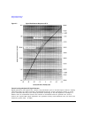
The flatness correction array contains 28 frequency correction pairs (amplitude correction values for
specified frequencies), from 26.5 to 40 GHz in 500 MHz intervals. This will result in 28 evenly spaced
flatness corrected frequencies between 26.5 GHz and 40 GHz at the output of the 83554A
millimeter-wave source module.
An Agilent E4416A/17A/18B/19B power meter (controlled by the signal generator via GPIB) and
R8486A power sensor are used to measure the RF output amplitude of the millimeter-wave source
module at the specified correction frequencies and transfer the results to the signal generator. The
signal generator reads the power level data from the power meter, calculates the correction values,
and stores the correction pairs in the user flatness correction array.
If you do not have the required Agilent power meter, or if your power meter does not have a GPIB
interface, you can enter correction values manually.