


Chapter 3 103
Basic Digital Operation
Triggering Waveforms
• Polarity determines the state of the trigger to which the waveform responds (used only with an
external trigger source); you can set either negative, or positive.
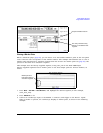
Source
Mode and Response
The arbitrary waveform player provides four trigger modes; each mode has one or more possible
responses:
•
Single plays the waveform once. Arb formats have the following retriggering options:
—
Off ignores triggers received during play; a trigger received after playback completes restarts
the playback.
—
On causes a trigger received during play to repeat the waveform after the current play
completes.
—
Immediate causes a trigger received during play to immediately restart the waveform.
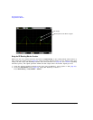
•
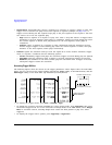
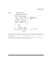
Gated causes the waveform to wait for the first active trigger signal state to begin transmission,
then repeatedly start and stop in response to an externally applied gating signal (example on
page 105). You select the active state with the
Gate Active Low High softkey (see page 105).
In an ARB format, the waveform plays during the inactive state, and stops during the active
state.
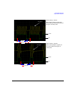
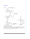
In real-time Custom, behavior depends on whether the signal incorporates framed or unframed
data.
Because the PSG provides only unframed data, to transmit a framed data signal you must create
an external file that incorporates the framing and download it to the PSG (see the E8257D/67D
PSG Signal Generators Programming Guide).
— Unframed data transmits during active states, and stops during inactive states. The signal
stops at the last transmitted symbol and restarts at the next symbol.
— Framed data starts transmitting at the beginning of a frame during active states, and stops at
the end of a frame when the end occurs during inactive states. If the end of the frame
extends into the next active state, the signal transmits continuously.
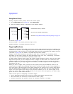
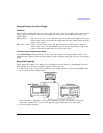
The Trigger hardkey
A command sent through the rear-panel GPIB, LAN, or Auxiliary (RS-232) interface
An external trigger signal applied to either the PATTERN TRIG IN connector, or the PATT TRIG IN 2
pin on the AUXILIARY I/O connector (connector locations are shown in Figure 1-3 on page 18).
The following parameters affect an external trigger signal:
• The source (Input connector) of the external trigger signal (see page 104)
• The polarity of the external trigger (described on page 105)
• Any desired delay between when the PSG receives an external trigger and when the
waveform responds to it (see page 104).