


Chapter 4 123
Optimizing Performance
Creating and Applying User Flatness Correction
For example, leveling the CW output of a 30 dB gain amplifier to a level of −10 dBm requires the
output of the signal generator to be approximately −40 dBm when leveled. This is beyond the
amplitude limits of the ALC modulator alone, resulting in an unleveled RF output. Inserting 45 dB of
attenuation results in an ALC level of +5 dBm, well within the range of the ALC modulator.
NOTE In the example above, 55 dB is the preferred attenuation choice, resulting in an ALC level of
+15 dBm. This provides adequate dynamic range for AM or other functions that vary the RF
output amplitude.
To achieve the optimum ALC level at the signal generator RF output of −40 dBm for an unmodulated
carrier, follow these steps:
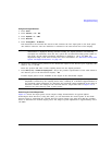
1. Press
Amplitude > Set Atten > 45 > dB.
2. Press Set ALC Level > 5 > dBm.
This sets the attenuator to 45 dB and the ALC level to +5 dBm, resulting in an RF output amplitude
of -40 dBm, as shown in the AMPLITUDE area of the display.
To obtain flatness-corrected power, refer to “Creating and Applying User Flatness Correction” on
page 123.
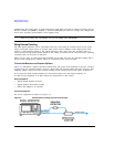
To Level with a mm-Wave Source Module
Millimeter-wave source module leveling is similar to external detector leveling. The power level
feedback signal to the ALC circuitry is taken from the millimeter-wave source module, rather than
the internal signal generator detector. This feedback signal levels the RF output power at the
mm-wave source module output through the signal generator’s rear panel SOURCE MODULE interface
connector.
For instructions and setups, see Chapter 11, “ Peripheral Devices,” on page 203.
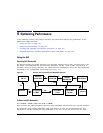
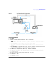
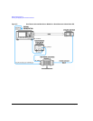
Creating and Applying User Flatness Correction
User flatness correction allows the digital adjustment of RF output amplitude for up to 1601
frequency points in any frequency or sweep mode. Using an Agilent E4416A/17A or E4418B/19B
power meter (controlled by the signal generator through GPIB) to calibrate the measurement system,
a table of power level corrections is created for frequencies where power level variations or losses
occur. These frequencies may be defined in sequential linear steps or arbitrarily spaced.
To allow different correction arrays for different test setups or different frequency ranges, you may
save individual user flatness correction tables to the signal generator’s memory catalog and recall
them on demand.
Use the steps in the next sections to create and apply user flatness correction to the signal
generator’s RF output.
Afterward, use the steps in “Recalling and Applying a User Flatness Correction Array” on page 127
to recall a user flatness file from the memory catalog and apply it to the signal generator’s RF
output.