


98 Chapter 3
Basic Digital Operation
Using Waveform Markers
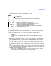
2. Toggle the markers as desired:
a. Highlight the first waveform segment.
b. Press
Enable/Disable Markers.
c. As desired, press
Toggle Marker 1, Toggle Marker 2, Toggle Marker 3, and Toggle Marker 4.
Toggling a marker that has no marker points (page 95) has no effect on the auxiliary outputs.
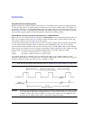
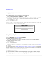
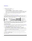
An entry in the Mkr column (see figure below) indicates that the marker is enabled for that
segment; no entry in the column means that all markers are disabled for that segment
d. In turn, highlight each of the remaining segments and repeat Step c.
3. Press
Return.
4. Name and store the waveform sequence (Step 3 on page 85).
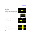
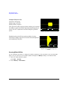
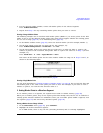
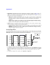
The following figure shows a sequence built reusing the same factory-supplied waveform segment; a
factory-supplied segment has a marker point on the first sample for all four markers. In this
example, Marker 1 is enabled for the first segment, Marker 2 is enable for the second segment, and
markers 3 and 4 are enabled for the third segment.
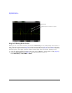
For each segment, only the markers enabled for that segment produce a rear-panel auxiliary output
signal. In this example, the Marker 1 auxiliary signal appears only for the first segment, because it is
disabled for the remaining segments. The Marker 2 auxiliary signal appears only for the second
segment, and the marker 3 and 4 auxiliary signals appear only for the third segment.
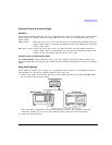
In an Existing Waveform Sequence
If you have not already done so, create and store a waveform sequence that contains at least three
segments (page 85). Ensure that the segment or segments are available in volatile memory (page 88).
1. Press
Mode > Dual ARB > Waveform Sequences, and highlight the desired waveform sequence.
2. Press
Edit Selected Waveform Sequence, and highlight the first waveform segment.
3. Press
Enable/Disable Markers > Toggle Marker 1, Toggle Marker 2, Toggle Marker 3, and Toggle Marker 4.
Toggling a marker that has no marker points (page 95) has no effect on the auxiliary outputs.
An entry in the Mkr column indicates that the marker is enabled for that segment; no entry in the
column means that all markers are disabled for that segment
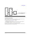
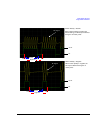
4. Highlight the next waveform segment and toggle the desired markers (in this example, markers 1
and 4).
5. Repeat Step 4 as desired (for this example, select the third segment and toggle marker 3).
6. Press
Return > Name And Store > Enter.
The markers are enabled or disabled per your selections, and the changes have been saved to the
selected sequence file.
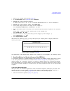
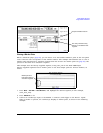
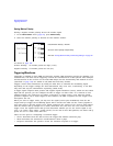
Sequence Marker Column
This entry shows that
markers 3 and 4 are enabled
for this segment.