


26 Chapter 1
Signal Generator Overview
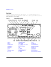
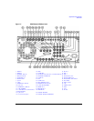
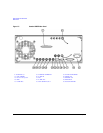
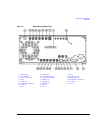
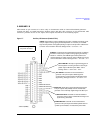
Rear Panel
14. Q-bar OUT
This female BNC connector (E8267D only) can be used with an internal baseband generator
(Option 601/602) to output the complement of the analog, quadrature-phase component of I/Q
modulation. On signal generators without Option 601/602, this female BNC connector can be used to
output the complement of the quadrature-phase component of an external I/Q modulation that has
been fed into the Q input connector.
Q-bar OUT is used in conjunction with Q OUT to provide a balanced baseband stimulus. Balanced
signals are signals present in two separate conductors that are symmetrical relative to ground and
are opposite in polarity (180 degrees out of phase). The nominal output impedance of the Q-bar OUT
connector is 50 ohms, dc-coupled.
15. AC Power Receptacle
The ac line voltage is connected here. The power cord receptacle accepts a three-pronged power cable
that is shipped with the signal generator.
16. GPIB
This GPIB interface allows listen and talk capability with compatible IEEE 488.2 devices.
17. 10 MHz EFC
This female BNC input connector (Options UNR/UNX only) accepts an external dc voltage, ranging
from −5 V to +5 V, for electronic frequency control (EFC) of the internal 10 MHz reference oscillator.
This voltage inversely tunes the oscillator about its center frequency (approximately −0.0025 ppm/V).
The nominal input impedance is greater than 1 Mohms. When not in use, this connector should be
shorted using the supplied shorting cap to assure a stable operating frequency.
18. ALC HOLD (Serial Prefixes >=US4722/MY4722)
This female BNC connector (E8267D only) is a TTL-compatible input that controls ALC action with
bursted I/Q signals from an arbitrary waveform generator (AWG). A high signal allows the ALC to
track the RF signal and maintain constant RF output level as the I/Q inputs vary. A low input signal
allows the ALC to be held for a brief time (less than 1 second) and not track the RF signal. When
driving the external I/Q inputs from an external arbitrary waveform generator supplying a bursted
waveform, the ALC Hold line should be driven from a marker output from the AWG that is high when
the bursted signal is at the proper level and low when the bursted signal is not at the proper level
Damage levels are > 5.5 V and < −0.5 V.