


102 Chapter 3
Basic Digital Operation
Triggering Waveforms
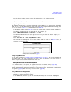
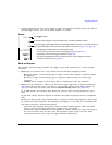
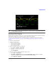
Setting Marker Polarity
Setting a negative marker polarity inverts the marker signal.
1. In the
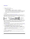
Marker Utilities menu (page 92), press Marker Polarity.
2. Select the marker polarity as desired for each marker number.
As shown on page 100:
Positive Polarity: On marker points are high (≈3.3V).
Negative Polarity: On marker points are low (0V).
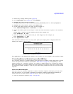
Triggering Waveforms
Triggering is available in both ARB and real-time formats. ARB triggering controls the playback of a
waveform file; real-time custom triggering controls the transmission of a data pattern. The examples
and discussions in this section use the Dual ARB Player, but the functionality and method of access
(described on page 104) are similar in all (ARB and real-time) formats.
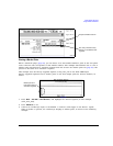
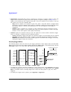
Triggers control data transmission by telling the PSG when to transmit the modulating signal.
Depending on the trigger settings, the data transmission may occur once, continuously, or the PSG
may start and stop the transmission repeatedly (Gated mode).
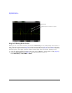
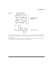
A trigger signal comprises both positive and negative signal transitions (states), which are also called
high and low periods; you can configure the PSG to trigger on either state. It is common to have
multiple triggers, also referred to as trigger occurrences or trigger events, occur when the signal
generator requires only a single trigger. In this situation, the PSG recognizes the first trigger event
and ignores the rest.
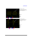
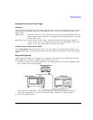
When you select a trigger mode, you may lose the signal (carrier plus modulation) from the RF
output until you trigger the modulating signal. This is because the PSG sets the I and Q signals to
zero volts prior to the first trigger event, which suppresses the carrier. If you create a data pattern
with the initial I and Q voltages set to values other than zero, this does not occur. After the first
trigger event, the signal’s final I and Q levels determine whether you see the carrier signal or not
(zero = no carrier, other values = visible carrier). At the end of most data patterns, the final I and Q
points are set to a value other than zero.
There are four parts to configuring a waveform trigger:
• Source determines how the PSG receives the trigger that initiates waveform play.
• Mode determines the waveform’s overall behavior when it plays.
• Response determines the specifics of how the waveform responds to a trigger.
Default Marker Polarity = Positive
Set each marker polarity independently.
See Also: “Saving Marker Polarity and Routing Settings” on page 90.