


Chapter 3 89
Basic Digital Operation
Using Waveform Markers
• “Using the RF Blanking Marker Function” on page 100
• “Setting Marker Polarity” on page 102
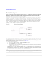
Waveform Marker Concepts
The signal generator’s ARB formats provide four waveform markers to mark specific points on a
waveform segment. You can set each marker’s polarity and marker points (on a single sample point
or over a range of sample points). Each marker can also perform ALC hold or RF Blanking and ALC
hold.
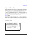
Marker File Generation
Generating a waveform segment (see page 84) automatically creates a marker file that places a
marker point on the first sample point of the segment for markers one and two.
Downloading a waveform file (as described in the E8257D/67D PSG Signal Generators Programming
Guide) that does not have a marker file associated with it creates a marker file that does not place
any marker points.
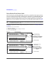
Marker Point Edit Requirements
Before you can modify a waveform segment’s marker points, the segment must reside in volatile
memory (see “Loading Waveform Segments from Non-volatile Memory” on page 88).
In the dual ARB player, you can modify a waveform segment’s marker points without playing the
waveform, or while playing the waveform in an ARB modulation format.
In an ARB modulation format, you must play the waveform before you can modify a segment’s
marker points.
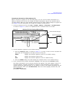
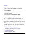
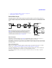
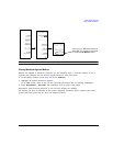
Marker
File
Bit N
Marker
Polarity
Marker N
RF Blank Off On
Marker N
Blanks RF
when Marker
is Low
EVENT N
Negative
Positive
Set Marker
On Off
Marker N
ALC Hold Off On
Marker N
Holds ALC
when Marker
is Low
When the signal generator encounters an enabled marker (described on
page 97), an auxiliary output signal is generated and routed to the rear
panel event connector that corresponds to the marker number (N).
The EVENT 3 and 4 connectors are pins on the AUXILIARY I/O connector
(connector locations are shown in Figure 1-3 on page 18).
RF Blank Only: includes ALC Hold