


Chapter 11 215
Peripheral Devices
N5102A Digital Signal Interface Module
Clock Timing for Serial Data
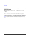
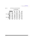
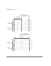
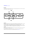
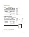
Figure 11-6 shows the clock timing for a serial port configuration. Notice that the serial transmission
includes frame pulses that mark the beginning of each sample while the clock delineates the
beginning of each bit. For serial transmission, the clock and the bit rates are the same, but the
sample rate varies depending on the number of bits per word that are entered using the
Word Size
softkey. The number of bits per word is the same as the number of bits per sample.
Figure 11-6 Clock Timing for a Serial Port Configuration
Clock Timing for Phase and Skew Adjustments
The N5102A module provides phase and skew adjustments for the clock relative to the data and can
be used to align the clock with the valid portion of the data. The phase has a 90 degree resolution
(0, 90, 180, and 270 degree selections) for clock rates from 10 to 200 MHz and a 180 degree
resolution (0 and 180 degree selections) for clock rates below 10 MHz and greater than 200 MHz.
The skew is displayed in nanoseconds with a maximum range of ±5 ns using a maximum of ±127
discrete steps. Both the skew range and the number of discrete steps are variable with a dependency
on the clock rate. The skew range decreases as the clock rate is increased and increases as the clock
rate is decreased. The maximum skew range is reached at a clock rate of approximately 99 MHz and
is maintained down to a clock rate of 25 MHz. For clock rates below 25 MHz, the skew adjustment is
unavailable.
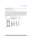
A discrete step is calculated using the following formula:
The number of discrete steps required to reach the maximum skew range decreases at lower
frequencies. For example, at a clock rate of 50 MHz, 127 steps would exceed the maximum skew
range of ±5 ns, so the actual number of discrete steps would be less than 127.
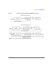
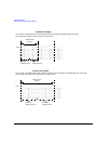
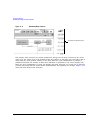
Figure 11-7 is an example of a phase and skew adjustment and shows the original clock and its
phase position relative to the data after each adjustment. Notice that the skew adjustment adds to
the phase setting.
Clock
4 bits per word
1 Sample
Frame Marker
Data Bits
1
256 Clock Rate×
------------------------------------------