


Chapter 4 129
Optimizing Performance
Creating and Applying User Flatness Correction
NOTE User Flatness correction is only applicable for Agilent 83550 series mm-wave source modules
and does not function with other mm-wave modules such as OML modules.
Required Equipment
• Agilent 83554A millimeter-wave source module
• Agilent E4416A/17A/18B/19B power meter
• Agilent R8486A power sensor
• Agilent 8349B microwave amplifier (required for signal generators without Option 1EA)
• GPIB interface cable
• adapters and cables as required
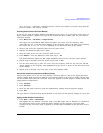
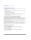
NOTE The equipment setups in Figure 4-5 and Figure 4-6 assume that the steps necessary to
correctly level the RF output have been followed. If you have questions about leveling with a
millimeter-wave source module, refer to “To Level with a mm-Wave Source Module” on
page 123.
Configure the Power Meter
1. Select SCPI as the remote language for the power meter.
2. Zero and calibrate the power sensor to the power meter.
3. Enter the appropriate power sensor calibration factors into the power meter as appropriate.
4. Enable the power meter’s cal factor array.
NOTE For operating information on your particular power meter/sensor, refer to their operating
guides.
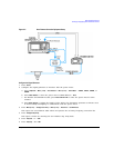
Connect the Equipment
CAUTION To prevent damage to the signal generator, turn off the line power to the signal
generator before connecting the source module interface cable to the rear panel SOURCE
MODULE interface connector.
1. Turn off the line power to the signal generator.
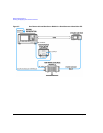
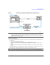
2. Connect the equipment. For standard signal generators, use the setup in Figure 4-5. For Option
1EA signal generators, use the setup in Figure 4-6.
NOTE During the process of creating the user flatness correction array, the power meter is slaved
to the signal generator via GPIB. No other controllers are allowed on the GPIB interface.