


12 Chapter 1
Signal Generator Overview
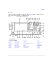
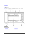
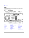
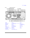
Front Panel
25. Return
Pressing this hardkey displays the previous softkey menu. It enables you to step back through the
menus until you reach the first menu you selected.
26. Contrast Decrease
Pressing this hardkey causes the display background to darken.
27. Contrast Increase
Pressing this hardkey causes the display background to lighten.
28. Local
Pressing this hardkey deactivates remote operation and returns the signal generator to front-panel
control.
29. Preset
Pressing this hardkey sets the signal generator to a known state (factory or user-defined).
30. Line Power LED
This green LED indicates when the signal generator power switch is set to the on position.
31. LINE
In the on position, this switch activates full power to the signal generator; in standby, it deactivates
all signal generator functions. In standby, the signal generator remains connected to the line power
and power is supplied to some internal circuits.
32. Standby LED
This yellow LED indicates when the signal generator power switch is set to the standby condition.
33. SYMBOL SYNC
This female BNC input connector is CMOS-compatible and accepts an externally supplied symbol sync
signal for use with the internal baseband generator (Option 601/602). The expected input is a 3.3 V
CMOS bit clock signal (which is also TTL compatible). SYMBOL SYNC might occur once per symbol or
be a single one-bit-wide pulse that is used to synchronize the first bit of the first symbol. The
maximum clock rate is 50 MHz. The damage levels are > +5.5 V and < −0.5V. The nominal input
impedance is not definable. SYMBOL SYNC can be used in two modes:
• When used as a symbol sync in conjunction with a data clock, the signal must be high during the
first data bit of the symbol. The signal must be valid during the falling edge of the data clock
signal and may be a single pulse or continuous.